Flexible film and display device including the same

Inactive Publication Date: 2009-12-03
LG ELECTRONICS INC
View PDF14 Cites 0 Cited by
  • Summary
  • Abstract
  • Description
  • Claims
  • Application Information

AI Technical Summary

Benefits of technology

[0010]Embodiments provide a flexible film with excellent stability

Problems solved by technology

In the sputtering method, because the surface of the polyimide film is damaged, the smoothness is reduced.
In the casting method, kinds of usable polyimide film

Method used


Image

  • Flexible film and display device including the same
  • Flexible film and display device including the same
  • Flexible film and display device including the same

Examples


Example

[0030]Reference will now be made in detail embodiments of the invention examples of which are illustrated in the accompanying drawings.

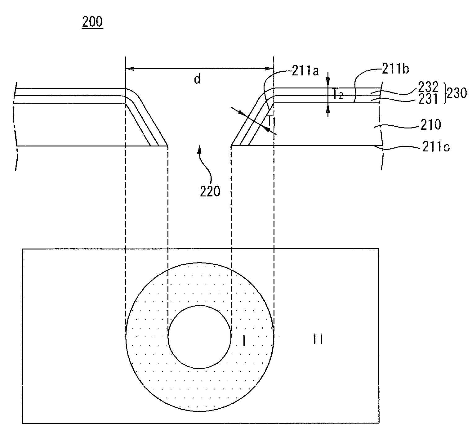
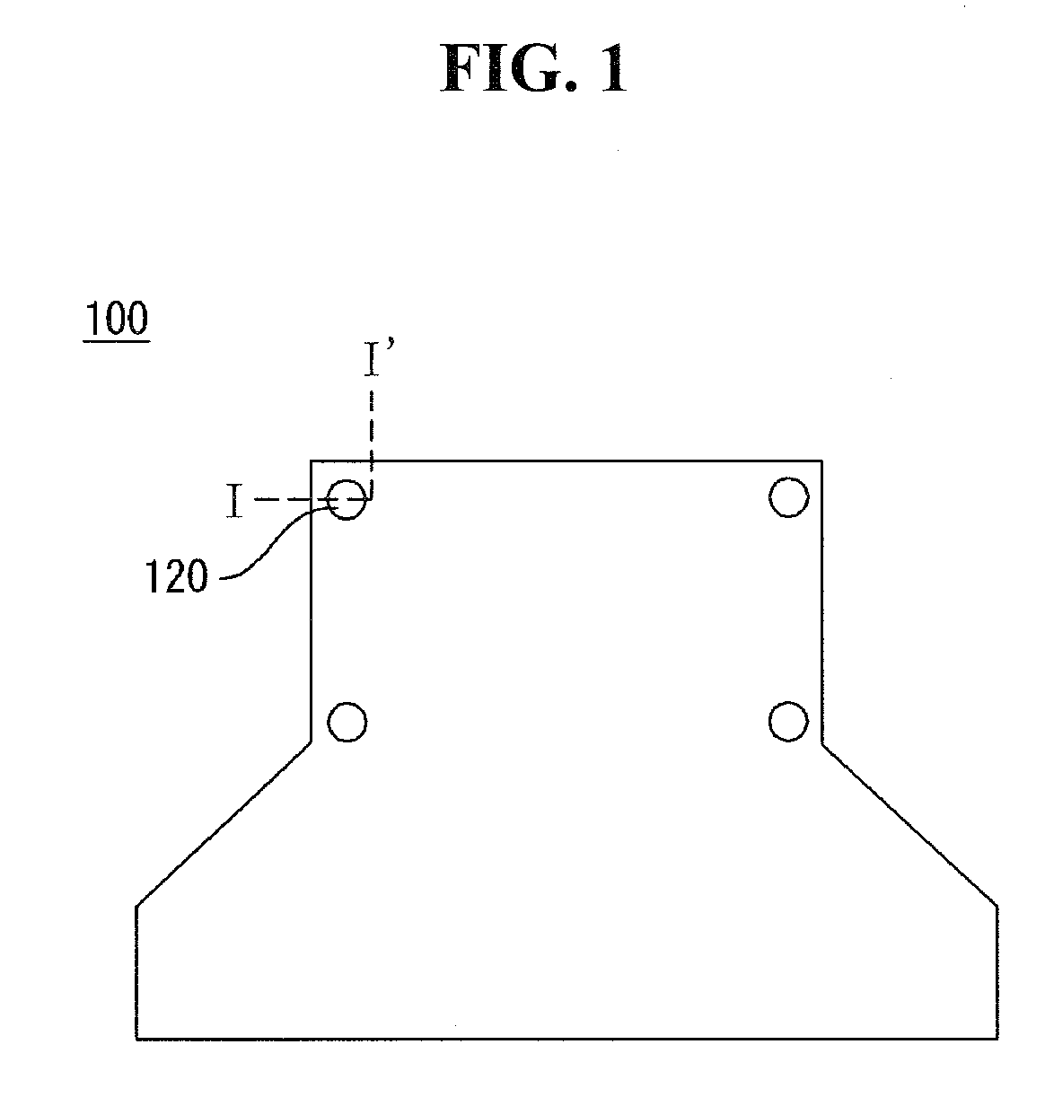
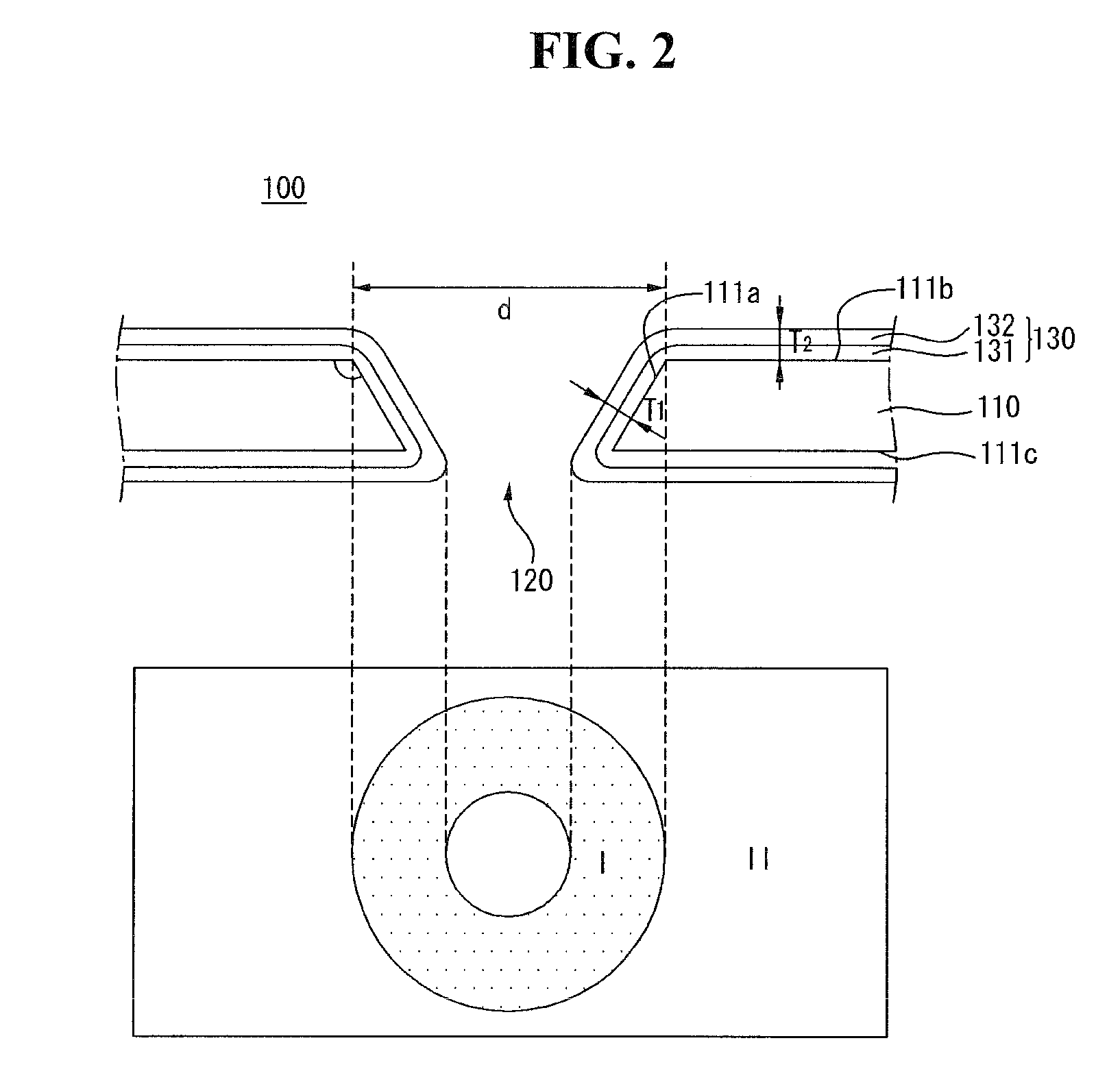
[0031]FIG. 1 shows a flexible film according to an exemplary embodiment, and FIGS. 2 to 4 are cross-sectional views taken along line I-I′ of FIG. 1.

[0032]As shown in FIGS. 1 to 4, a flexible film 100 according to an exemplary embodiment is used in a tape automated bonding (TAP) method. The flexible film 100 is connected to a panel.

[0033]The flexible film 100 may include an insulating film 110 including a hole 120, an inner surface 111a surrounding the hole 120, a first surface 111b, and a second surface 111c opposite the first surface 111b and a metal layer 130 covering the inner surface 111a and at least one of the first and second surfaces 111b and 111c. The metal layer 130 may include a first layer 131 and a second layer 132. The metal layer 130 may have a first portion I corresponding to the inner surface 111a and a second portion II correspondin...


PUM


Abstract

A flexible film and a display device including the same are provided. The flexible film includes an insulating film including a hole, an inner surface surrounding the hole, a first surface, and a second surface opposite to the first surface and a metal layer covering the inner surface and at least one of the first and second surfaces. The metal layer includes a first layer and a second layer. The metal layer has a first portion on the inner surface and a second portion on the first surface or the second surface. The first portion has a thickness smaller than a thickness of the second portion.

Description

[0001]This application claims the benefit of Korean Patent Application No. 10-2008-0049492 filed on May 28, 2008, the entire contents of which is hereby incorporated by reference.BACKGROUND[0002]1. Field[0003]Embodiments relate to a flexible film, and more particularly, to a flexible film used in a display device.[0004]2. Description of the Related Art[0005]A flexible film may be a component necessarily used in thin profile display devices. As an example of the flexible film, there may be a flexible printed circuit board (FPCB) and a flexible copper clad laminate (FCCL).[0006]A metal layer of the FPCB or the FCCL is manufactured using a sputtering method, a casting method, or a laminating method.[0007]In the sputtering method, a sputtering process is performed on a polyimide film to form a metal layer. In the casting method, liquid polyimide is coated on a metal thin film, and then a casting process is performed to thereby form a metal layer of the FCCL. In the laminating method, an...

Claims


Application Information

Patent Timeline
IPC IPC(8): G09G3/20B32B3/10
CPCH05K1/0393H05K3/181H05K3/426Y10T428/24331H05K2201/09827H05K2201/10681H05K2201/0344H05K3/46H05K1/02
Inventor YUM, JUNGSUPKO, DONGKI
Owner LG ELECTRONICS INC
Why Eureka
Try Eureka