Image sensor and image-capturing device

a technology which is applied in the field of image sensor and image capture device, can solve the problems of poor focus detection accuracy and achieve the effect of poor focus detection accuracy and less precision

Active Publication Date: 2009-12-03
NIKON CORP
View PDF5 Cites 69 Cited by
  • Summary
  • Abstract
  • Description
  • Claims
  • Application Information

AI Technical Summary

Benefits of technology

[0006]There is still a challenge to be addressed in the image sensor in the related art described above in that a pair of focus detection light fluxes having passed through different areas of the exit pupil of the photographic optical system enter photoelectric conversion elements

Problems solved by technology

There is still a challenge to be addressed in the image sensor in the related art described above in that a pair of focus detection light fluxes having passed through different areas of the exit pupil of the photographic optical system enter photoelectric conversion elements wit

Method used


Image

  • Image sensor and image-capturing device
  • Image sensor and image-capturing device
  • Image sensor and image-capturing device

Examples


Embodiment Construction

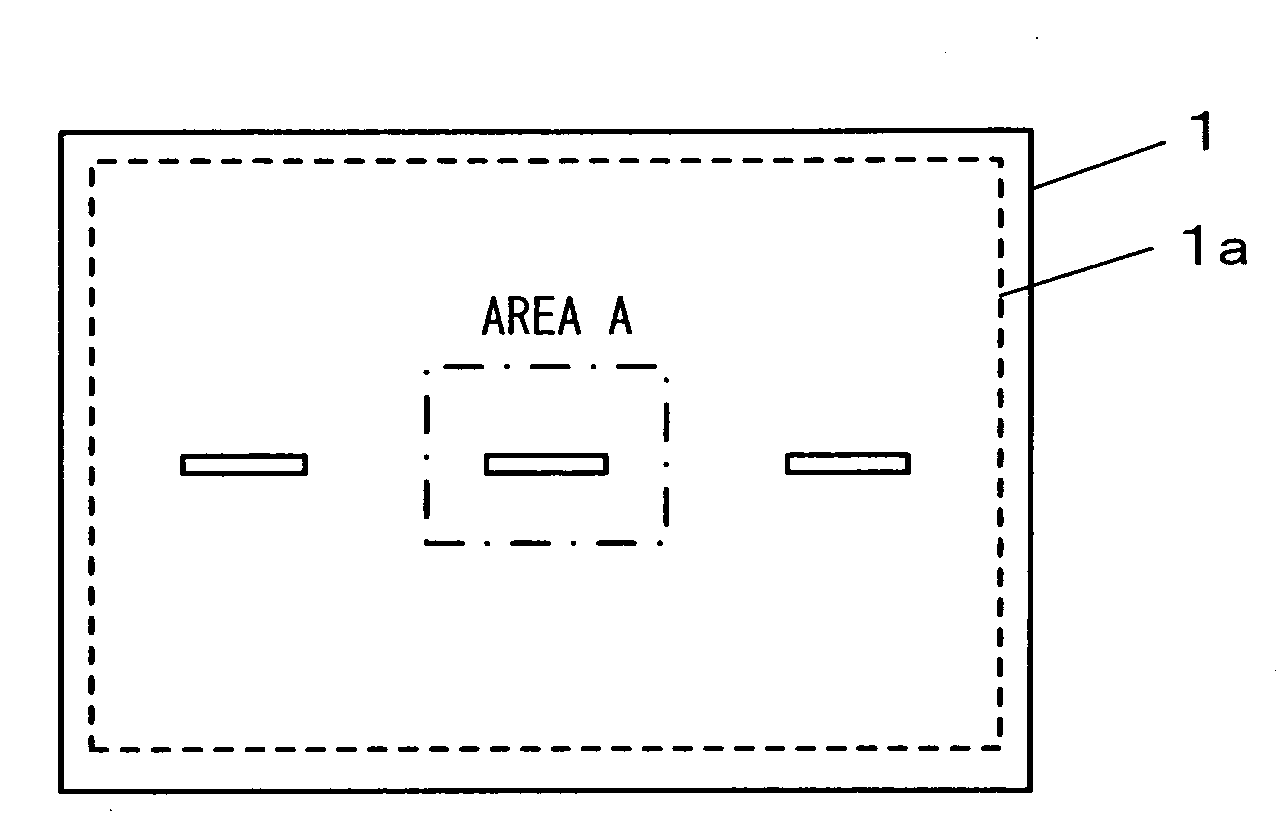
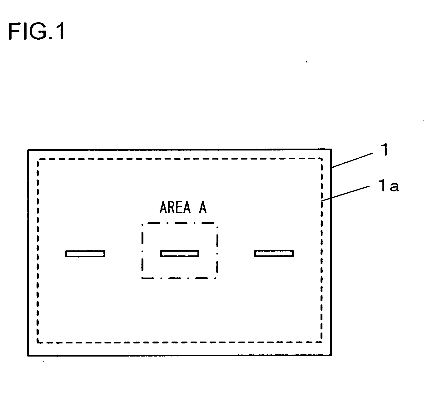
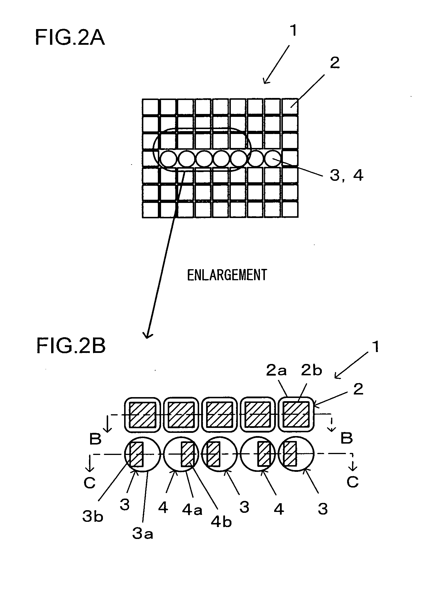
[0029]FIG. 1 is a front view of the image sensor achieved in an embodiment. The image sensor 1 in the embodiment includes imaging pixels disposed in a two-dimensional array within its effective pixel area 1a, with focus detection pixels disposed over part of the array, i.e., over a central area and areas to the left and to the right of the central area within the effective pixel area 1a. FIG. 2A shows the central area A in the image sensor 1 shown in FIG. 1 in an enlargement, whereas FIG. 2B shows part of FIG. 2A in a further enlargement. In addition, FIG. 3A shows the image sensor 1 in FIG. 2B in a section taken through B-B, whereas FIG. 3B shows the image sensor 1 in FIG. 2B in a section taken through C-C. It is to be noted that FIG. 2B shows photoelectric conversion elements disposed under micro-lenses as well.

[0030]As shown in FIGS. 3A and 3B, the image sensor 1 is formed by attaching a photoelectric conversion element array 6, with a plurality of photoelectric conversion elemen...


PUM


Abstract

An image sensor includes: a plurality of imaging pixels; and a plurality of focus detection pixels constituted with a micro-lens and a photoelectric conversion element that receives a focus detection light flux transmitted through a photographic optical system and executes photoelectric conversion. The photoelectric conversion element in each of the focus detection pixels includes a light-receiving area where the focus detection light flux is received; light-receiving area images corresponding to each of the focus detection pixels are each formed as the light-receiving area is projected via the micro-lens onto a pupil plane of the photographic optical system; and a positional relationship of the micro-lens and the light-receiving area is determined in correspondence to an image height so that the light-receiving area images corresponding to all the focus detection pixels are superimposed on one another on the pupil plane.

Description

INCORPORATION BY REFERENCE[0001]This non-provisional application claims the benefit of U.S. Provisional Application No. 61 / 129,045 filed Jun. 2, 2008. This application also claims priority from Japanese Patent Application No. 2008-144209 filed Jun. 2, 2008. The disclosure of each of the earlier applications is incorporated herein by reference in its entirety.BACKGROUND OF THE INVENTION[0002]1. Field of the Invention[0003]The present invention relates to an image sensor and an image-capturing device, used to capture a subject image.[0004]2. Description of Related Art[0005]Japanese Laid Open Patent Publication No. 2000-156823 discloses an image sensor that includes focus detection pixels disposed over part of a two-dimensional imaging pixel array, captures a subject image formed via a photographic optical system and detects the focusing condition of the photographic optical system through a split-pupil phase difference detection method.SUMMARY OF THE INVENTION[0006]There is still a ch...

Claims


Application Information

Patent Timeline
IPC IPC(8): H04N5/335G02B7/34G03B13/36H01L27/14H04N5/232
CPCH04N5/2254H04N5/345H04N5/23212H01L27/14627H04N23/672H04N25/44H04N25/704
Inventor UTAGAWA, KENKUSAKA, YOSUKE
Owner NIKON CORP
Why Eureka
Try Eureka