Method of measuring position error of beam of exposure apparatus and exposure apparatus using the same

a technology of position error and beam, which is applied in the direction of photomechanical equipment, instruments, printers, etc., can solve the problems of high mask cost and process cost increase, and achieve the effects of less influence on the environment, uniform exposure quality, and more precisely measured

Inactive Publication Date: 2009-12-03
SAMSUNG ELECTRONICS CO LTD
View PDF3 Cites 4 Cited by
  • Summary
  • Abstract
  • Description
  • Claims
  • Application Information

AI Technical Summary

Benefits of technology

[0010]The present invention has been made in an effort to provide a method of measuring a position error of a beam of an exposure apparatus and an exposure apparatus using the same having advantages of briefly measuring a position of a beam within a short time period in an exposure apparatus that does not use a mask.
[0017]The exposure apparatus may further include: a controller that controls the DMD element; an optical transmission means such as an optical fiber that transfers light from the light source to the DMD element and an optical path change means such as a reflector or a beam splitter; and an optical system that performs a function of concentrating focuses of beams that are selectively radiated from the DMD and of extending a distance between the beams.
[0031]As described above, according to the present invention, because a position error of an exposure beam is determined using a radiation amount of an exposure beam that is radiated through a pinhole of the mask, it is unnecessary to move a mask. When a DMD passes on a measurement mark, as in an existing method (Japanese Patent Laid-Open Publication No. 2006-308997), because there is no drawback in which a very long repetition measurement time period is required as only a very few columns are measured according to a size of a sensor, a time period for detecting a position error of an exposure beam and a correcting time period of an experiment including the exposure beam are shortened. Thereby, an influence of an environment can be minimized and a laser can be more precisely measured. When using this method, because a position error of an exposure beam is simply and rapidly detected, a radiation amount can be constantly controlled upon exposing and a uniform exposure quality can be obtained.

Problems solved by technology

Because the manufacturing cost of the mask is high, when a new mask is formed, the process cost increases.
However, even in a light exposer that does not use the mask, a process of correcting the light exposer is required, as in a light exposer that uses a mask.

Method used


Image

  • Method of measuring position error of beam of exposure apparatus and exposure apparatus using the same
  • Method of measuring position error of beam of exposure apparatus and exposure apparatus using the same
  • Method of measuring position error of beam of exposure apparatus and exposure apparatus using the same

Examples


Embodiment Construction

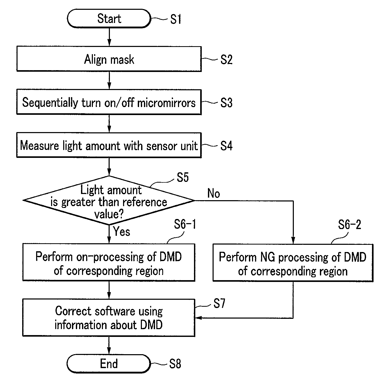
[0041]An exposure apparatus according to an embodiment of the present invention is described with reference to FIGS. 1 to 3.

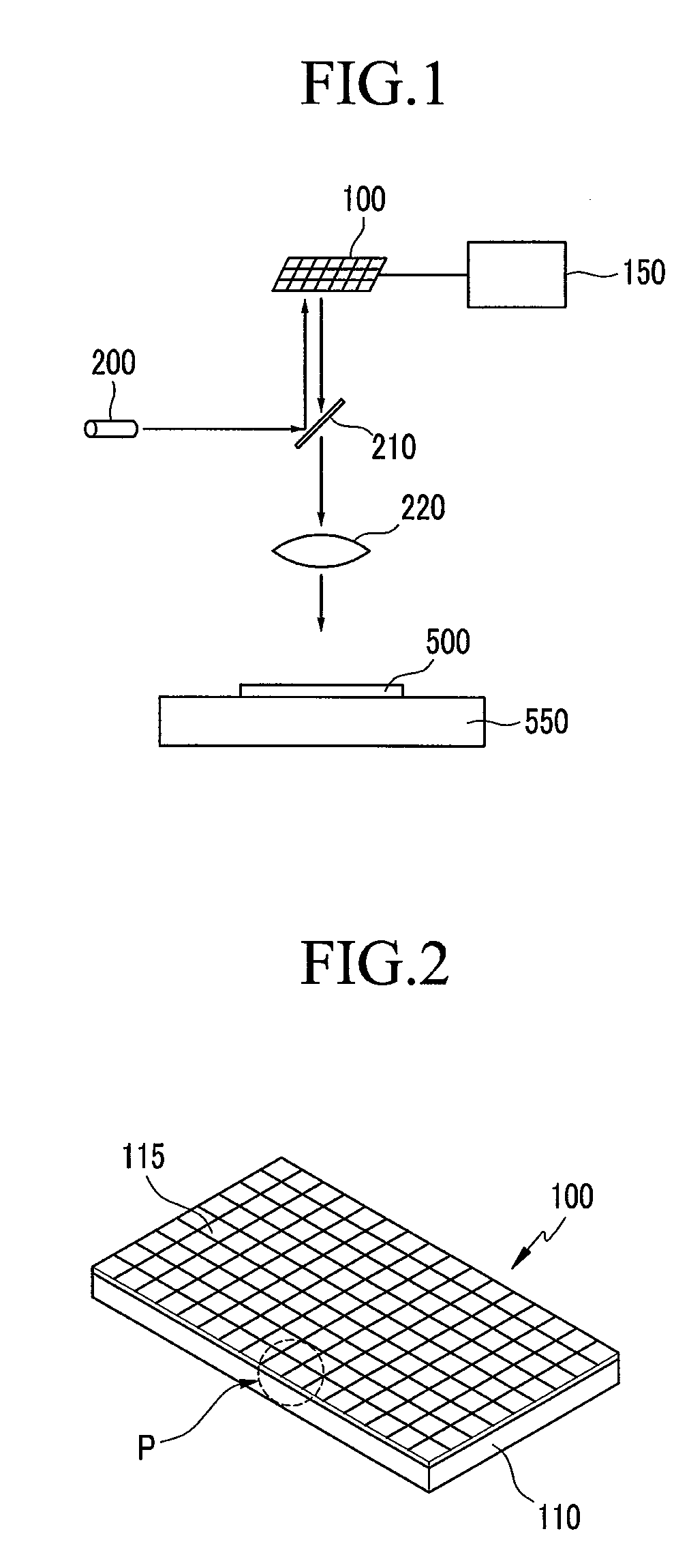
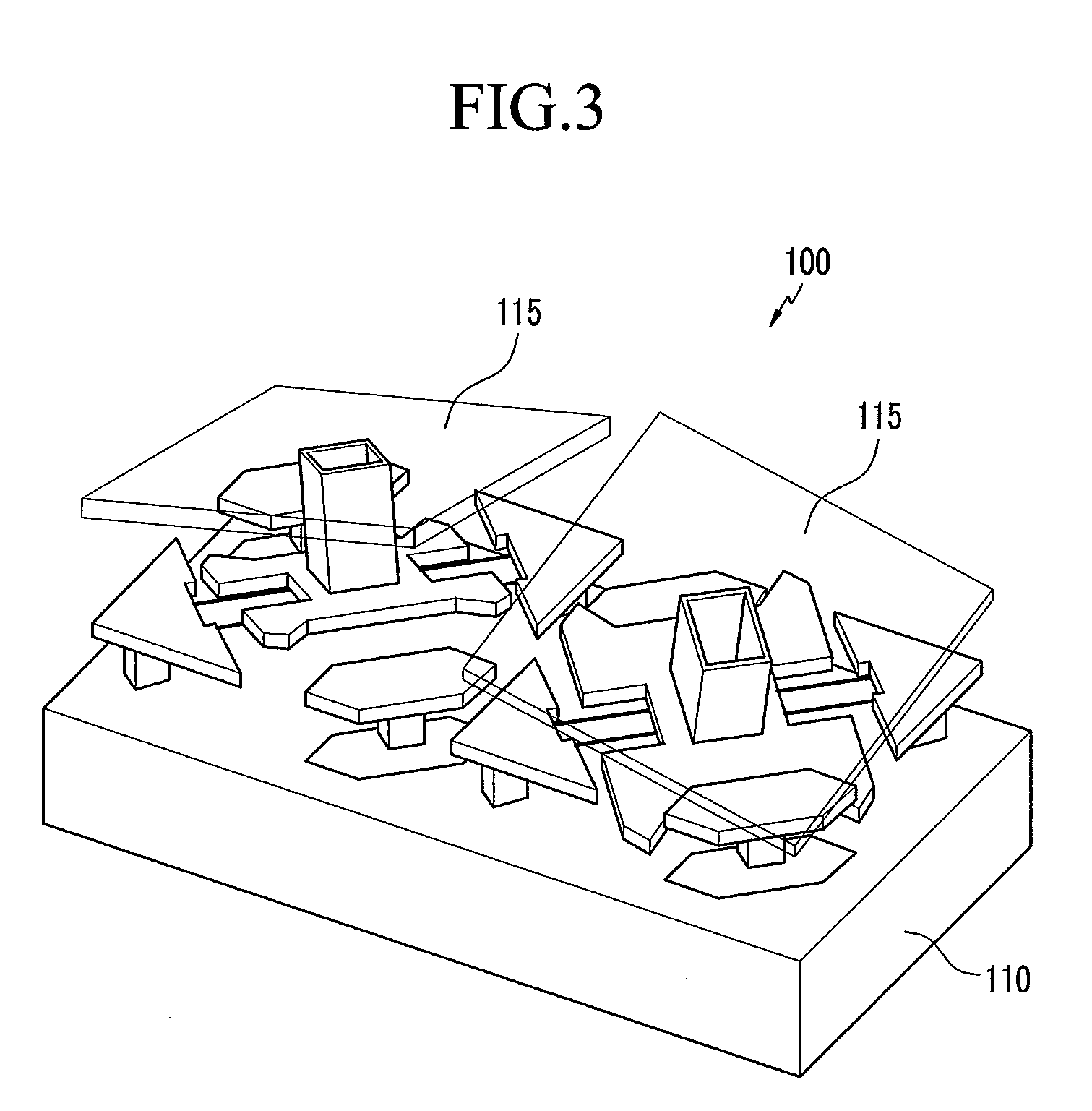
[0042]FIG. 1 illustrates a configuration of an exposure apparatus according to an embodiment of the present invention, FIG. 2 illustrates a DMD element of the exposure apparatus according to an embodiment of the present invention, and FIG. 3 illustrates an operation of the DMD element according to an embodiment of the present invention.

[0043]The exposure apparatus according to an embodiment of the present invention uses a DMD element 100 instead of a mask. Specifically, the exposure apparatus includes the DMD element 100, a controller 150, a light source 200, a beam splitter 210, an optical system 220, a mask 500, and a sensor unit 550. Although not all shown in the drawings, the exposure apparatus may include a device for correcting a focus of an exposure beam, a substrate 110 to which an exposure beam is radiated, a stage for transporting the substrate, a sta...


PUM


Abstract

A method of measuring a position error of a beam of an exposure apparatus and an exposure apparatus using the same are provided. An exposure apparatus using a digital micromirror device (DMD) element instead of a mask measures a radiation amount of a beam that passes through each pinhole using a mask including a pinhole, and when the radiation amount is less than a reference value, it is determined that an exposure beam has a position error. By using the exposure apparatus and a method of measuring a position error of a beam, a measurement time period is reduced, and a position error of a beam is simply and accurately determined.

Description

CROSS-REFERENCE TO RELATED APPLICATION[0001]This application claims priority to and the benefit of Korean Patent Application No. 10-2008-0050236 filed in the Korean Intellectual Property Office on May 29, 2008, the entire contents of which are incorporated herein by reference.BACKGROUND OF THE INVENTION[0002](a) Field of the Invention[0003]The present invention relates to a method of measuring a position error of a beam of an exposure apparatus, and an exposure apparatus using the same.[0004](b) Description of the Related Art[0005]A liquid crystal display or a plasma display device performs a photolithography process in order to form a pixel and wiring. In general, in an exposure process of a photolithography process, a mask is used and an exposure beam is radiated through an opening of the mask.[0006]However, masks should be individually formed in each pattern, and when a new pattern is formed, the mask should be newly formed. Because the manufacturing cost of the mask is high, whe...

Claims


Application Information

Patent Timeline
Patent Type & Authority Applications(United States)
IPC IPC(8): G03B27/54G01B9/02
CPCG03B27/54G03F7/7085G03F7/70516G03F7/70291G03F7/20
Inventor PARK, SANG-HYUNJANG, SANG-DONLEE, HI-KUKKIM, JEONG-MIN
Owner SAMSUNG ELECTRONICS CO LTD
Why Eureka
Try Eureka