Lighting system

a technology of light-emitting system and light-emitting device, which is applied in the direction of fixed installation, lighting and heating apparatus, and light-emitting support devices, etc., can solve the problems of difficult to effectively prevent the temperature of leds from rising, adversely affecting the service life, and the temperature drop of optical output. achieve the effect of reducing the degree of change in heat-radiating action

Inactive Publication Date: 2009-12-03
TOSHIBA LIGHTING & TECH CORP +1
View PDF8 Cites 48 Cited by
  • Summary
  • Abstract
  • Description
  • Claims
  • Application Information

AI Technical Summary

Benefits of technology

[0016]And, since heat can be radiated from the hanging element via an irradiation angle changing mechanism even if the irradiation ...

Problems solved by technology

With respect to light emitting elements such as LEDs, an increase in temperature lowers the optical output, varies the characteristics thereof and further adversely influences the service life thereof.
However, although Japanese Laid-Open Patent Publication No. 2005-71821 shows a concavo-convex shape for heat radiation on the rear side of the main body, it does not show a detailed he...

Method used


Image

  • Lighting system
  • Lighting system
  • Lighting system

Examples


embodiment 2

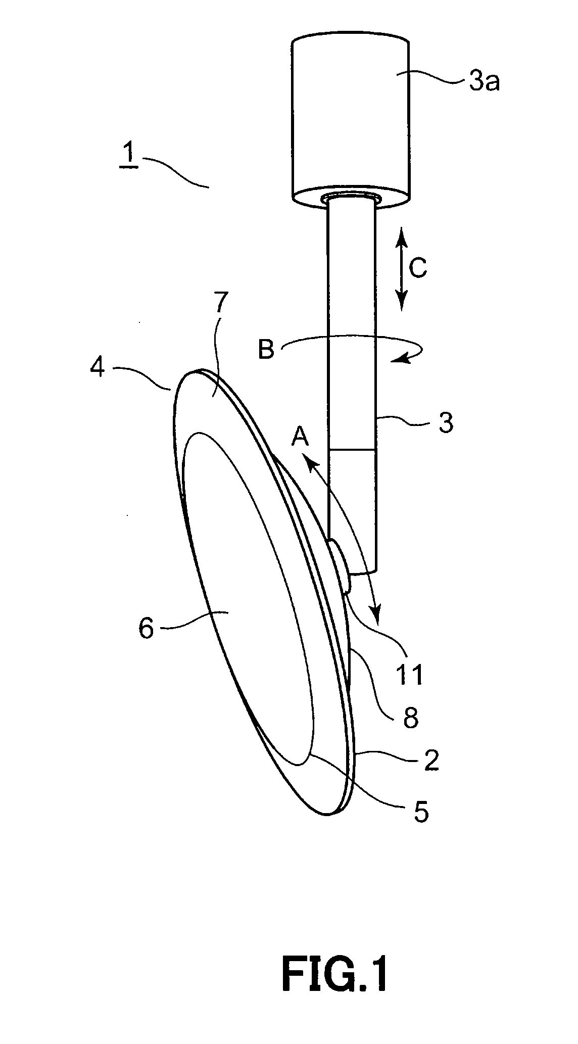
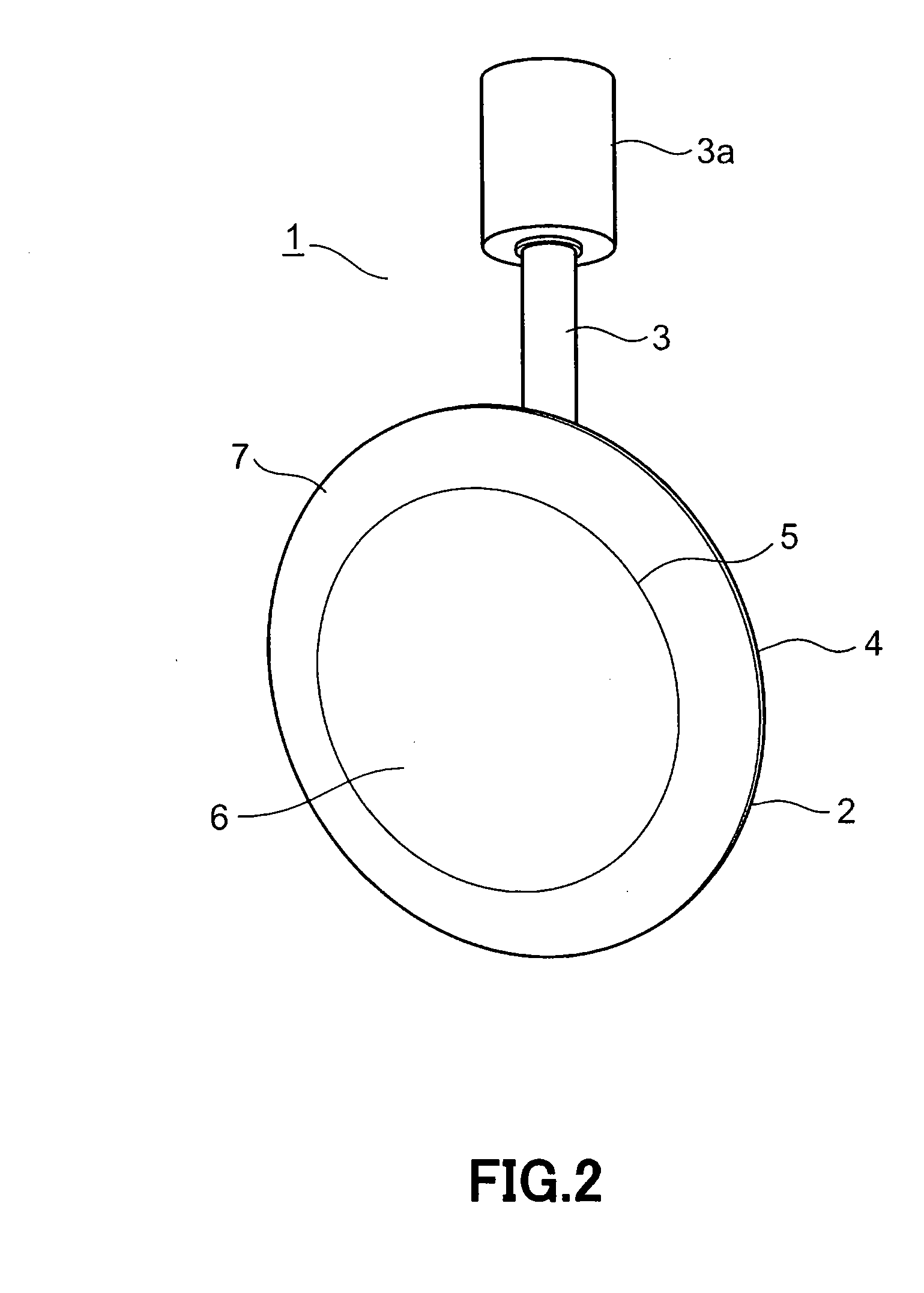
[0057]Next, a description is given of a lighting system of the present invention with reference to FIG. 7. FIG. 7 is a perspective view of a spotlight operating as the lighting system. Also, components that are identical to or correspond to those of the above embodiment are given the same reference numerals, and overlapping description thereof is omitted.

[0058]This embodiment differs from the above embodiment in view of a supporting structure of the main body casing 4. In the previous embodiment, a description was given of such a type in which the main body casing 4 is hung from a ceiling surface, etc., by the hanging rod 3 in use. However, this embodiment relates to such a type in which the main body casing 4 is placed in an opening portion H of a ceiling surface, etc., and both the ends of the main body casing 4 are supported so as to turn by a supporting rod 3-2.

[0059]Therefore, the elevation angle of the main body casing 4 can be adjusted, and the irradiation light can be turne...

embodiment 5

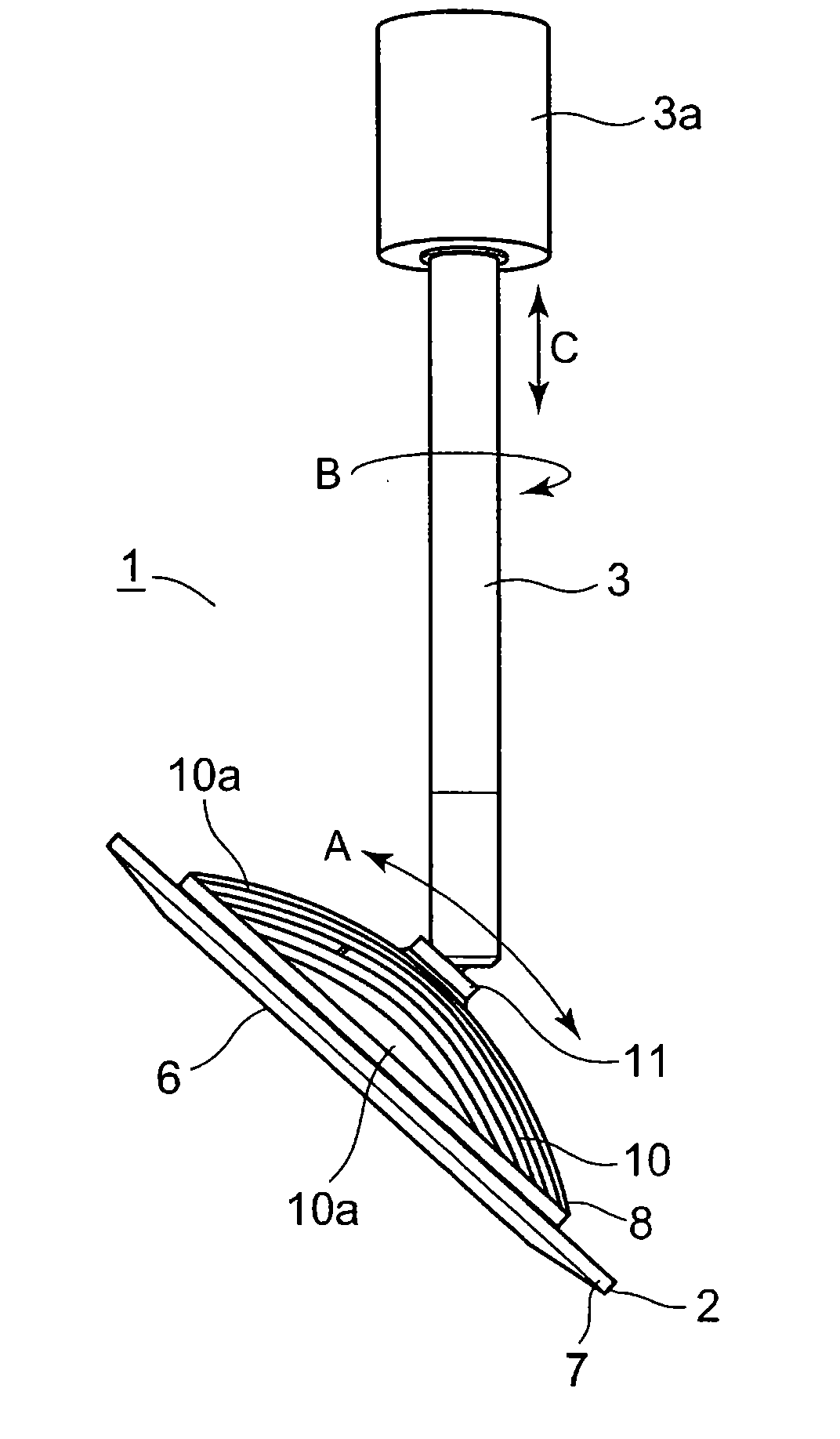
[0077]Next, a description is given of a lighting system according to the present invention with reference to FIG. 13 through FIG. 17. FIG. 13 is a side elevational view showing a spotlight as a lighting system. FIG. 14 is a side elevational view of the same spotlight, in which the angle in the elevation angle direction thereof is changed. FIG. 15 is a plan view of the same spotlight. FIG. 16 is a side elevational view schematically showing the shape of heat-radiating fins of the same spotlight. FIG. 17 is a side elevational view showing another example of the same spotlight. Also, components that are identical to or correspond to those of Embodiment 5 are given the same reference numerals, and overlapping description thereof is omitted.

[0078]This embodiment differs from previous embodiments in view of a configuration of the heat-radiating fin portion 10 at the rear side portion 8 of the main body casing 4. As shown in FIG. 13 through FIG. 16, a number of heat-radiating fins 10a, whi...


PUM


Abstract

A spotlight is provided with a substrate having LEDs disposed thereon and a main body casing on which the substrate is provided. The main body casing has a rear side portion having thermal conductivity, which is thermally coupled to the substrate, and is capable of changing the irradiation angle of light emitted from the LEDs. A plurality of heat-radiating fins for forming grooves operating as a plurality of convection paths along the direction of changing the irradiation angle are provided on the rear side portion of the main body casing.

Description

CROSS REFERENCE TO PRIOR APPLICATIONS AND INCORPORATION BY REFERENCE[0001]The present invention claims priority under 35 U.S.C. §119 to Japanese Patent Application Nos. 2008-139782 and 2009-061909 filed on May 28, 2008 and Mar. 13, 2009, respectively. The contents of these applications are incorporated herein by reference in their entirety.FIELD OF THE INVENTION[0002]The present invention relates to a lighting system, in which light emitting elements such as LEDs are used, capable of changing the irradiation angle of light.BACKGROUND OF THE INVENTION[0003]With respect to light emitting elements such as LEDs, an increase in temperature lowers the optical output, varies the characteristics thereof and further adversely influences the service life thereof. Therefore, in a light source unit using light emitting elements, for example, LEDs and EL elements as a light source, it is necessary to prevent the temperature of the light emitting elements from rising for the purpose of improving ...

Claims


Application Information

Patent Timeline
IPC IPC(8): F21V29/00F21S8/08F21K99/00
CPCF21S8/043F21S8/06F21V21/29F21V21/30F21V29/004F21Y2101/02F21V29/89F21V23/005F21V29/507F21V29/73F21V29/75F21V29/763F21V29/773F21Y2105/008F21Y2105/00F21Y2115/15F21Y2115/10
Inventor OGAWA, KOZOTAKAHASHI, AIKOBETSUDA, NOBUHIKOTAMAI, HIROKINISHIMURA, KIYOSHISAITO, AKIKOMATSUDA, RYOTARO
Owner TOSHIBA LIGHTING & TECH CORP
Why Eureka
Try Eureka