Side-loaded light emitting diode module for automotive rear combination lamps

a technology of light-emitting diodes and side-loaded diodes, which is applied in the direction of semiconductor devices for light sources, light and heating apparatus, transportation and packaging, etc., can solve the problems of disfavored option (a), unsatisfactory alteration of the angular output of the element, and hesitant to completely abandon the familiarity of a bulb/lamp with a socket and its accompanying traditional-style optics

Inactive Publication Date: 2009-12-03
OSRAM SYLVANIA INC
View PDF16 Cites 28 Cited by
  • Summary
  • Abstract
  • Description
  • Claims
  • Application Information

AI Technical Summary

Benefits of technology

[0038]FIG. 2 is a cross-sectional schematic drawing of a simplified optical path in a rear combination lamp, having a single LED and an un-faceted reflector.
[0039]FIG. 3 is a cross-sectional schematic drawing of a simplified optical path in a rear combination lamp, having multiple LEDs and an un-faceted reflector.
[0040]FIG. 4 is a cross-sectional schematic drawing of a simplified optical path in a rear combination lamp, having a single LED and a faceted reflector.

Problems solved by technology

Because there are spatial differences in output between LEDs and typical bulbs or lamps, it may not be feasible to simply swap an LED for an incandescent lamp in a particular lighting element; to do so may undesirably alter the angular output from the element.
While they have been eager to adopt LEDs for all of the advantages stated above, they have been hesitant to completely abandon the familiarity of a bulb / lamp with a socket and its accompanying traditional-style optics.
Option (a) is disfavored for a number of reasons, including access issues, styling issues, mechanical depth issues, and sealing the light set to the body issues.
This reduces cost and complexity, and ensures an effective seal against dirt and water, and (2) The mechanics of a removable lens cover is difficult, due to fit and styling issues.
One potential drawback to the lighting systems of these three references is that two separate elements are used to collimate and then reflect the beam.
These separate elements may be costly to fabricate, costly and time-consuming to align, and may introduce unnecessary loss into the optical system (i.e., some light may be absorbed, reflected and / or scattered out of the output beam by the multiple elements).

Method used


Image

  • Side-loaded light emitting diode module for automotive rear combination lamps
  • Side-loaded light emitting diode module for automotive rear combination lamps
  • Side-loaded light emitting diode module for automotive rear combination lamps

Examples


Embodiment Construction

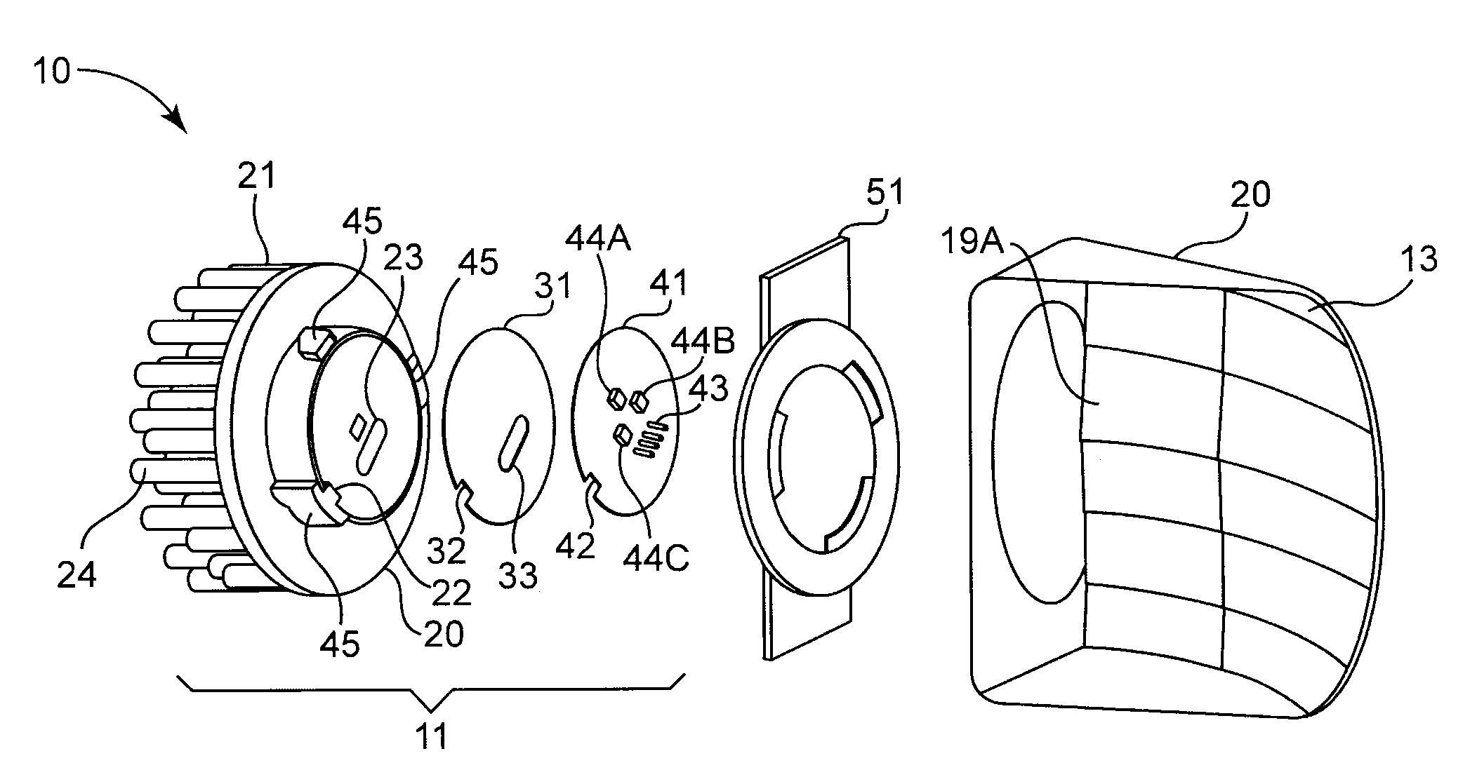
[0043]The light emitting diode (LED) module disclosed herein may be used for exterior vehicle lighting. The LED module may be installed in a light set socket from the side, rather than from the back. The LED module may include optical elements suitable to distribute the light to a reflector that receives light from the LED chip(s) and directs the reflected light toward a viewer. Because the LED module may be installed from the side, rather than the back, the reflector may be more compact than in conventional reflector designs. This is disclosed more fully in the detailed description below.

[0044]For typical, known rear combination lamps that use light emitting diodes as their light sources, there have been numerous ways of ensuring that the output light exits the device with the proper orientation. For instance, the first generation system commercially available with the name JOULE used light emitting diodes mounted at a particular angle. The assembly process for this first generatio...


PUM


Abstract

A side-loading LED module for a rear combination lamp is disclosed. One or more LEDs are mounted on a distal side of a printed circuit board, which also includes the circuitry that drives the one or more LEDs. The circuit board and a thermal pad are screwed/riveted to a heat sink, then the heat sink is mounted to a lateral face of a housing. The LEDs emit diverging light laterally inside the housing. One face of the housing is a faceted parabolic reflector, which receives the diverging light from the LEDs and reflects a collimated beam longitudinally to the front of the housing, where it passes through a clear cover and exits the lamp. The facets on the parabolic reflector angularly deviate portions of the reflected beam, so that the reflected light is collimated, and is angularly broader than a single collimated beam.

Description

CROSS-REFERENCE TO RELATED APPLICATIONS[0001]The present application claims priority under 35 U.S.C §119(e) to provisional application No. 61 / 056,738, filed on May 28, 2008 under the title, “Side entry LED light module for automotive rear combination lamp,” and incorporated by reference herein in its entirety. Full Paris Convention priority is hereby expressly reserved.STATEMENT REGARDING FEDERALLY SPONSORED RESEARCH OR DEVELOPMENT[0002]Not ApplicableBACKGROUND OF THE INVENTION[0003]1. Field of the Invention[0004]The present invention is directed to rear combination lamps for automotive lighting systems.[0005]2. Description of the Related Art[0006]For many years, automobiles have employed electric lighting that serves a variety of functions. For instance, lights provide forward illumination (headlamps, auxiliary lamps), conspicuity (parking lights in front, taillights in rear), signaling (turn signals, hazards, brake lights, reversing lights), and convenience (dome lights, dashboard...

Claims


Application Information

Patent Timeline
Patent Type & Authority Applications(United States)
IPC IPC(8): F21V7/06F21V7/00H01L33/58H01L33/60
CPCF21K9/00F21S48/1159F21S48/1376F21S48/211F21S48/215F21S48/23F21V29/81F21V7/0008F21V29/004F21Y2101/02F21V29/74F21V29/75F21V29/80F21S48/328F21Y2115/10F21S41/337F21S43/19F21S43/14F21S43/30F21S45/47B60Q1/26F21V23/00F21V29/00F21V29/89F21V29/76
Inventor LUO, HONGLIU, ZHAOHUAN
Owner OSRAM SYLVANIA INC
Why Eureka
Try Eureka