Method for manufacturing toner, toner, developer, developing device, and image forming apparatus

a technology of toner and developing device, which is applied in the direction of instruments, electrographic process equipment, and developers, can solve the problems of not directly applicable to toner inner core particles such as toners, poor productivity, and lowering the yield of coated particles, so as to achieve stable image formation, high definition, and high definition

Active Publication Date: 2009-12-03
SHARP KK
View PDF8 Cites 15 Cited by
  • Summary
  • Abstract
  • Description
  • Claims
  • Application Information

AI Technical Summary

Benefits of technology

[0050]According to the invention, an image forming apparatus is realized by comprising an image bearing member on which a latent image is to be formed; a latent image forming section for forming the latent image on the image bearing member; and the developing device capable

Problems solved by technology

However, the method disclosed in JP-B2 5-10971 causes the following problem.
When the powder particles and the coating material aggregate and grow in the inner wall of the apparatus, there occur problems that a powder passage for fluidizing the powder particles is narrowed and the powder particles are prevented from being isolated and fluidized and that the yield of the coated particles is lowered.
Further, there is a possibility that air bubbles are generated in the film of the fine resin particles when the liquid is dried, and the method disclosed in the JP-B 5-10971 (1993) is not directly applicable to resin inner c

Method used


Image

  • Method for manufacturing toner, toner, developer, developing device, and image forming apparatus
  • Method for manufacturing toner, toner, developer, developing device, and image forming apparatus
  • Method for manufacturing toner, toner, developer, developing device, and image forming apparatus

Examples


example 1

[Toner Base Particle Producing Step S1]

[0208]Raw materials of the toner base particles and addition amounts thereof were as follows:

Polyester resin (trade name: DIACRON,87.5% (100 parts) manufactured by Mitsubishi Rayon Co., Ltd., glasstransition temperature of 55° C., softeningtemperature of 130° C.)C.I. Pigment Blue 15:35.0% (5.7 parts)Release agent (Carunauba Wax, melting point of6.0% (6.9 parts)82° C.)Charge control agent (trade name: Bontron E84,1.5% (1.7 parts)manufactured by Orient Chemical Industries, Ltd.)

[0209]After pre-mixing each of the constituent materials described above by a Henschel mixer (trade name: FM20C, manufactured by Mitsui Mining Co., Ltd.), the obtained mixture was melt and kneaded by a twin-screw extruder (trade name: PCM65 manufactured by Ikegai, Ltd.). After coarsely pulverizing the melt-kneaded material by a cutting mill (trade name: VM-16, manufactured by Orient Co., Ltd.), it was finely pulverized by a jet mill (manufactured by Hosokawa Micron Corpora...

example 2

[0215]A toner of Example 2 was obtained in the same manner as Example 1 except for that the temperature of the powder flowing section of the apparatus was set to 40° C. and the temperature of the stirring section was not controlled at the coating step.

example 3

[0216]A toner of Example 3 was obtained in the same manner as Example 1 except for that the installation angle of the two-fluid nozzle was changed so that the angle formed by the liquid spraying direction and the powder flowing direction (hereinafter referred to as “spraying angle”) was 45° at the coating step.


PUM


Abstract

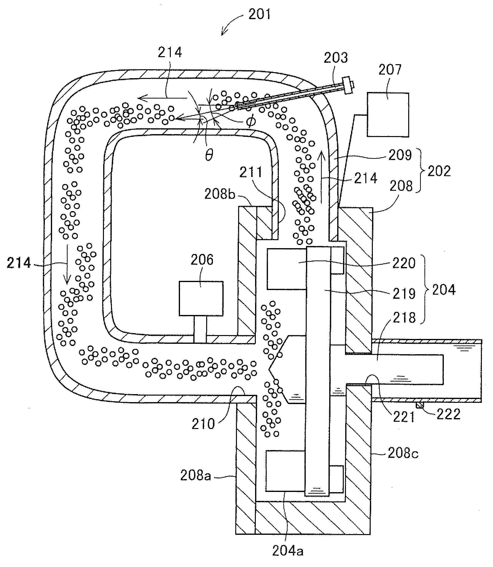
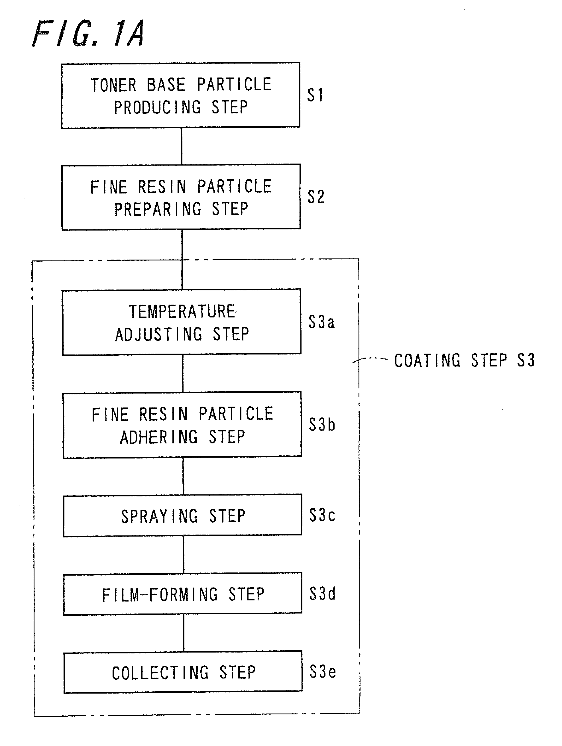
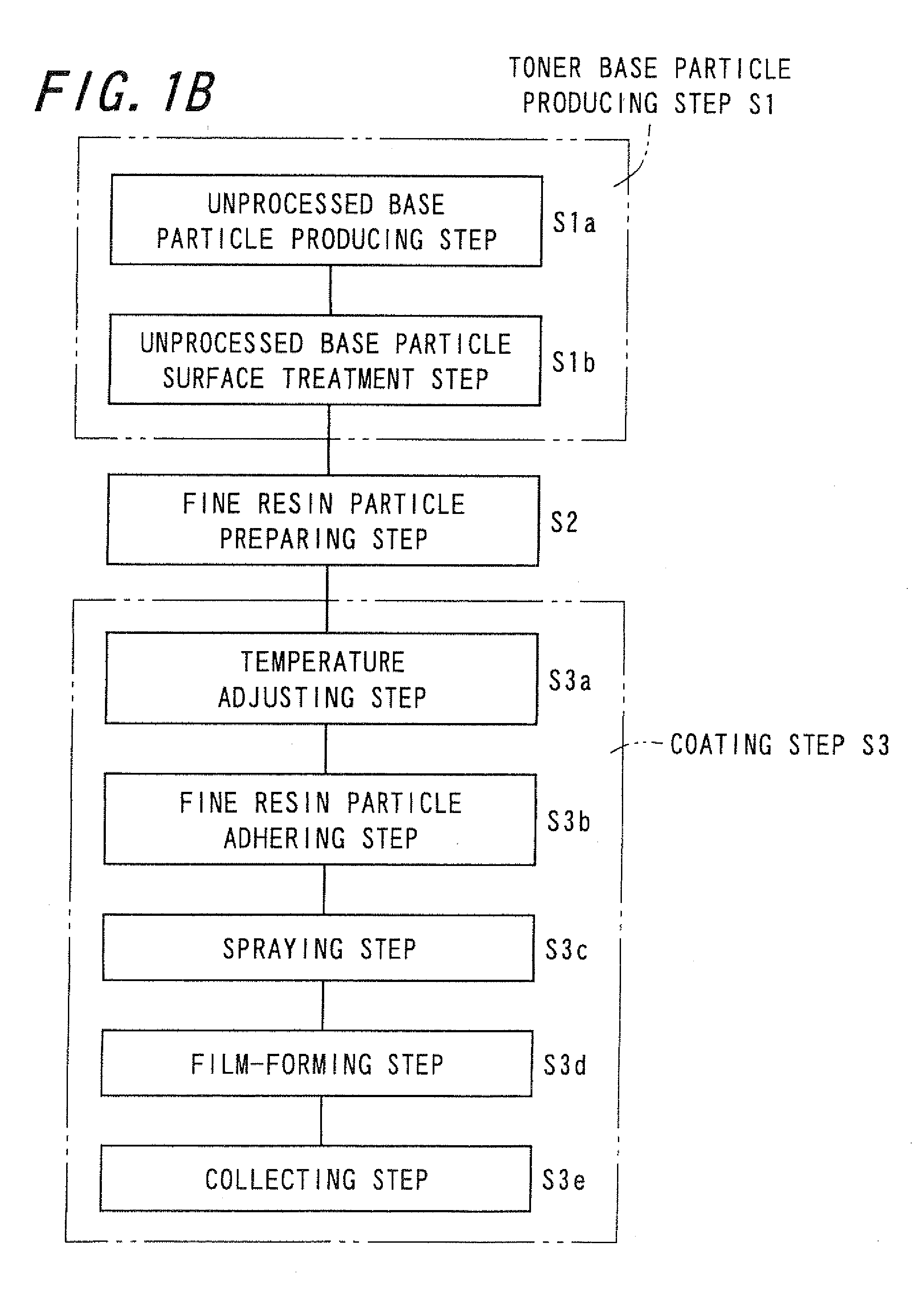
A method for manufacturing a toner is provided. The method for manufacturing a toner uses a rotary stirring apparatus that includes a circulating section for repeatedly performing circulation in a powder passage having a rotary stirring chamber and a circulation tube to return to the rotary stirring chamber by a rotary stirring section having a rotary disc around which rotary blades are installed and a rotary shaft, and a temperature adjusting section provided at least on a part of the powder passage for adjusting temperatures in the powder passage and of the rotary stirring section to a predetermined temperature, and includes a temperature adjusting step; a fine resin particle adhering step; a spraying step; and a film-forming step. The temperature in the powder passage is adjusted to the predetermined temperature by the temperature adjusting section at the fine resin particle adhering step, the spraying step, and the film-forming step.

Description

CROSS-REFERENCE TO RELATED APPLICATION[0001]This application claims priority to Japanese Patent Application Nos. 2008-143722 and 2009-006166, which were filed on May 30, 2008 and Jan. 14, 2009, respectively, the contents of which are incorporated herein by reference in its entirety.BACKGROUND OF THE INVENTION[0002]1. Field of the Invention[0003]The present invention relates to a method of manufacturing a toner, the toner, a developer, a developing device, and an image forming apparatus.[0004]2. Description of the Related Art[0005]Conventionally, a surface modification treatment for coating the surface of powder particles with a coating material has been performed in order to improve characteristics of the powder particles such as toner particles.[0006]As a method for the surface modification treatment of the powder particles such as toner particles, a method is known that a mechanical stirring force is applied to the powder particles by a rotary stirring section such as a screw, a b...

Claims


Application Information

Patent Timeline
IPC IPC(8): G03G15/08G03G9/093
CPCG03G9/0804G03G9/081G03G2215/0614G03G9/0827G03G9/09392G03G9/0815
Inventor KAWASE, YOSHITAKAYAMADA, SAORIAKAZAWA, YOSHIAKITSUBAKI, YORITAKAMUTOH, YOSHINORIKIKAWA, KEIICHIHARA, TAKASHI
Owner SHARP KK
Why Eureka
Try Eureka