
Digital Abutment For Dental Implant System

Inactive Publication Date: 2009-12-03
GLOBAL IMPLANT SOLUTIONS
View PDF58 Cites 21 Cited by
  • Summary
  • Abstract
  • Description
  • Claims
  • Application Information

AI Technical Summary

Benefits of technology

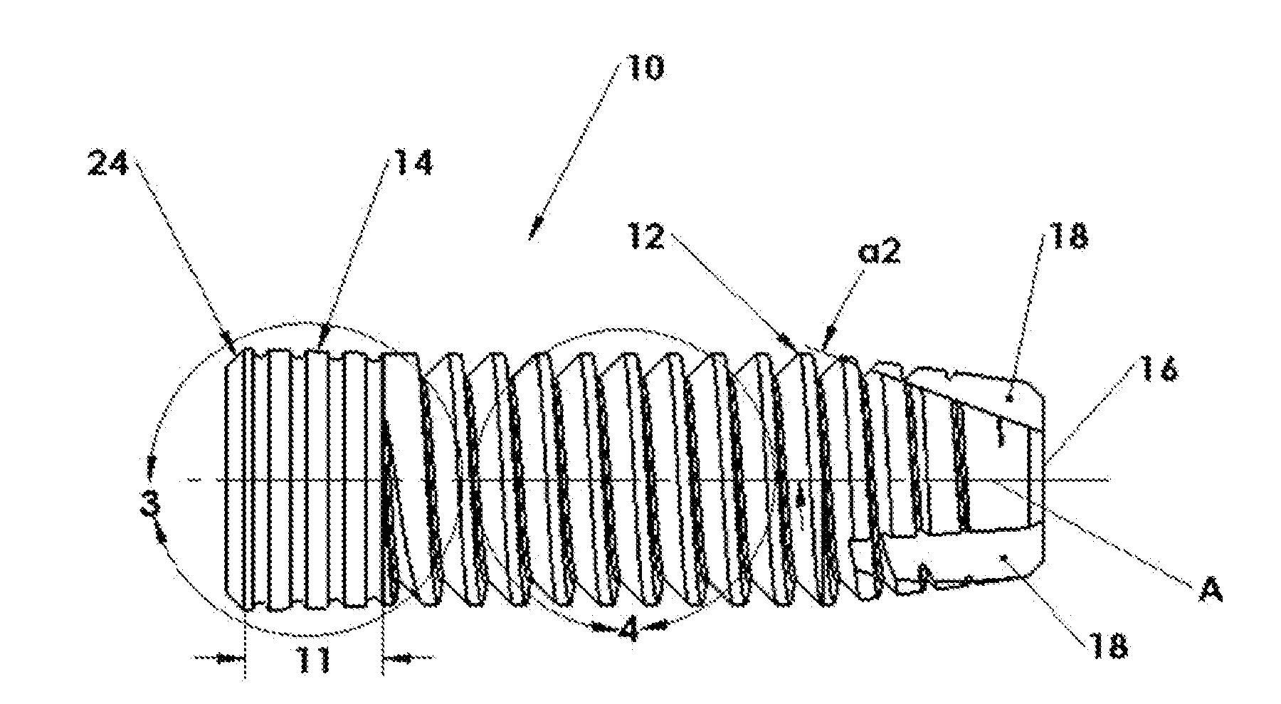
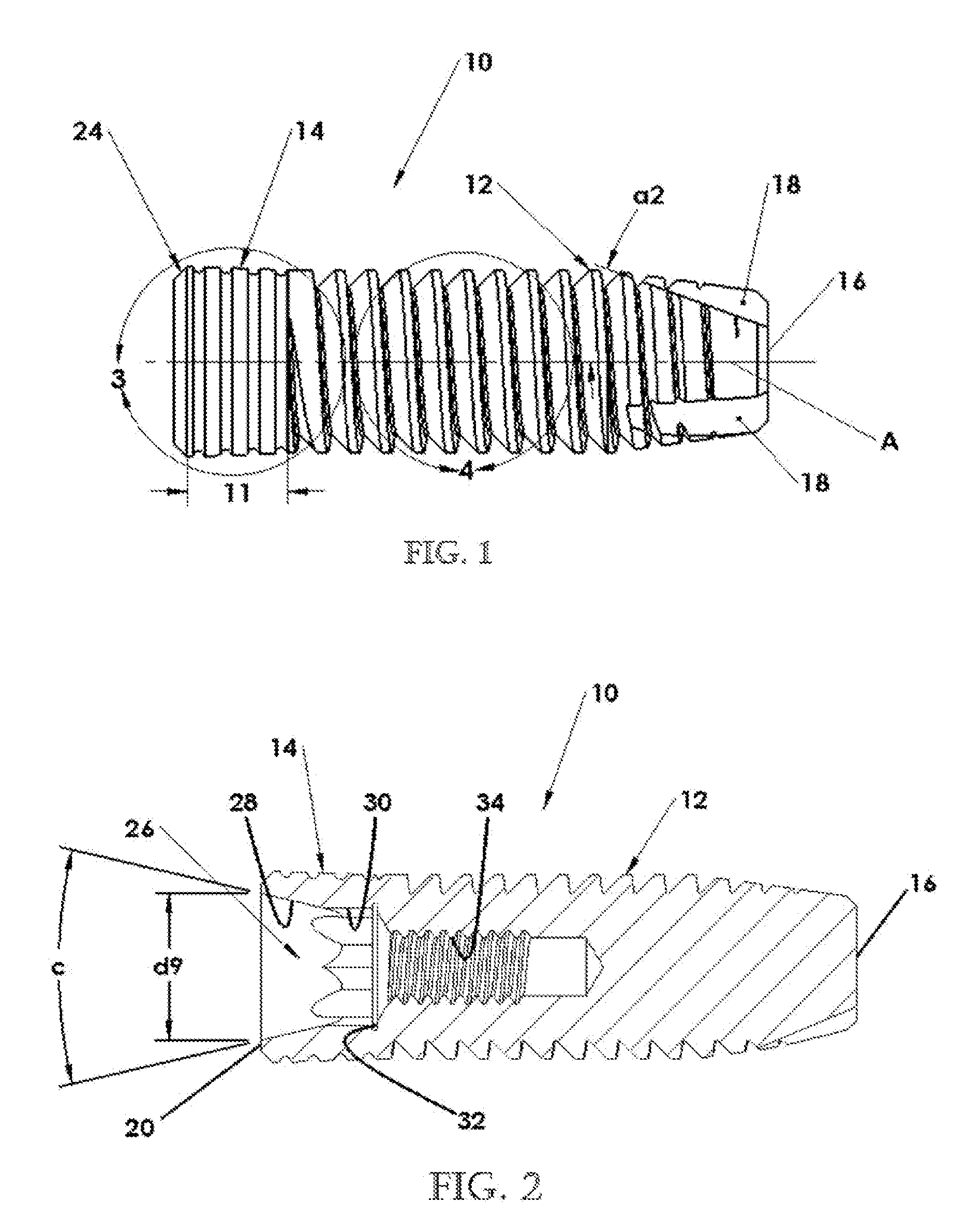
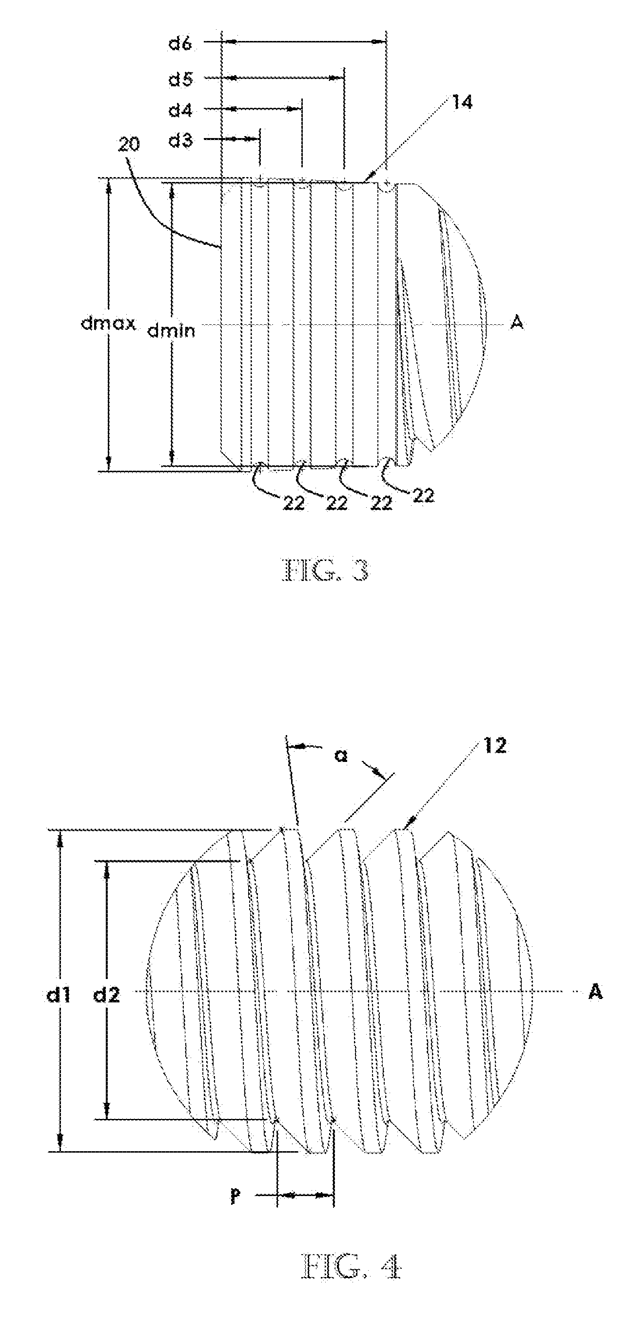
[0007]According to one aspect of the present disclosure, a dental implant includes a threaded shank portion and a head portion extending from the shank portion and including a recessed cavity in an axial end thereof. The recessed cavity has a cone shaped region extending from the axial end of the head portion and a multi-sided region extending from the cone shaped region in a direction extending away from the axial end of the head portion. The geometry of the multi-sided region provides for improved wall strength while maintaining a small head profile.
[0042]Upon receipt of the scan, the usual protocol is for the dental laboratory to fabricate a working model (Rapid prototype plastic model) using their specific method for producing a working model of the dental arch that includes the digital abutment. The working model is then used to create a standard silicone index of the model with the digital abutment. A Digital Abutment is attached to an implant analog and is then inserted into the silicone index that was made earlier. Soft tissue replication material is added around the connection between the digital abutment and the analog. The portion of the model that includes the digital abutment replica is removed along with a portion of the model containing it. The silicone index is seated over the model. This will result in the digital abutment / implant analog assembly to be positioned precisely in the space vacated by removing that portion from the model in the earlier step. Die stone or any similar material can be added around the implant analog to secure the implant analog to the model. This will produce a model that includes within it an implant analogue replicating the position of the implant in the mouth and avoiding the need for a chair side impression. It will also enable the dentist to use scanning technology to reproduce implant position and fabricate final restorations.

Problems solved by technology

One potential problem with dental implants having internal connections is that the interior cavity that defines the internal connection is surrounded by a thin wall portion.

Method used


Image

  • Digital Abutment For Dental Implant System
  • Digital Abutment For Dental Implant System
  • Digital Abutment For Dental Implant System

Examples


Embodiment Construction

[0024]Example embodiments will now be described more fully with reference to the accompanying drawings.

[0025]Example embodiments are provided so that this disclosure will be thorough, and will fully convey the scope to those who are skilled in the art. Numerous specific details are set forth such as examples of specific components, devices, and methods, to provide a thorough understanding of embodiments of the present disclosure. It will be apparent to those skilled in the art that specific details need not be employed, that example embodiments may be embodied in many different forms and that neither should be construed to limit the scope of the disclosure. In some example embodiments, well-known processes, well-known device structures, and well-known technologies are not described in detail.

[0026]The terminology used herein is for the purpose of describing particular example embodiments only and is not intended to be limiting. As used herein, the singular forms “a,”“an,” and “the” ...


PUM


Abstract

A digital abutment is provided to assist in taking digital impressions of a patient's mouth for design and manufacture of a prosthetic tooth. The digital abutment can receive a temporary crown so that the digital abutment can remain in place for preserving the gingival architecture while waiting for a final crown and a final abutment.

Description

CROSS-REFERENCE TO RELATED APPLICATIONS[0001]This application claims the benefit of U.S. Provisional Application No. 61 / 130,163 filed on May 28, 2008.FIELD[0002]The present disclosure relates to a dental implant system and more particularly, to a dental implant with an improved implant to abutment engagement geometry.BACKGROUND AND SUMMARY[0003]This section provides background information related to the present disclosure which is not necessarily prior art and provides a general summary of the disclosure, and is not a comprehensive disclosure of its full scope or all of its features.[0004]Dental implants are screwed or otherwise inserted into a prepared site in a jaw bone and serve as a fixture on which a prosthetic tooth or other dental appliance can be mounted. Dental implants have been in clinical use as a predictable treatment modality for more than 40 years and are well known in the art. Dental implants have various external shapes and generally fall into one of three categorie...

Claims


Application Information

Patent Timeline
IPC IPC(8): A61C8/00
CPCA61C8/0022A61C8/0066A61C8/005
Inventor AL-ATTAR, WASSEEM
Owner GLOBAL IMPLANT SOLUTIONS
Learn More