
Continuous cardiac marker sensor system

a sensor system and cardiac marker technology, applied in the field of continuous detection and/or measurement of cardiac markers in vivo, can solve the problems of increasing medical care costs, increasing the risk of heart disease, and slow process of obtaining cardiac marker concentrations, and affecting the treatment of patients

Inactive Publication Date: 2009-12-03
DEXCOM
View PDF6 Cites 810 Cited by
  • Summary
  • Abstract
  • Description
  • Claims
  • Application Information

AI Technical Summary

Benefits of technology

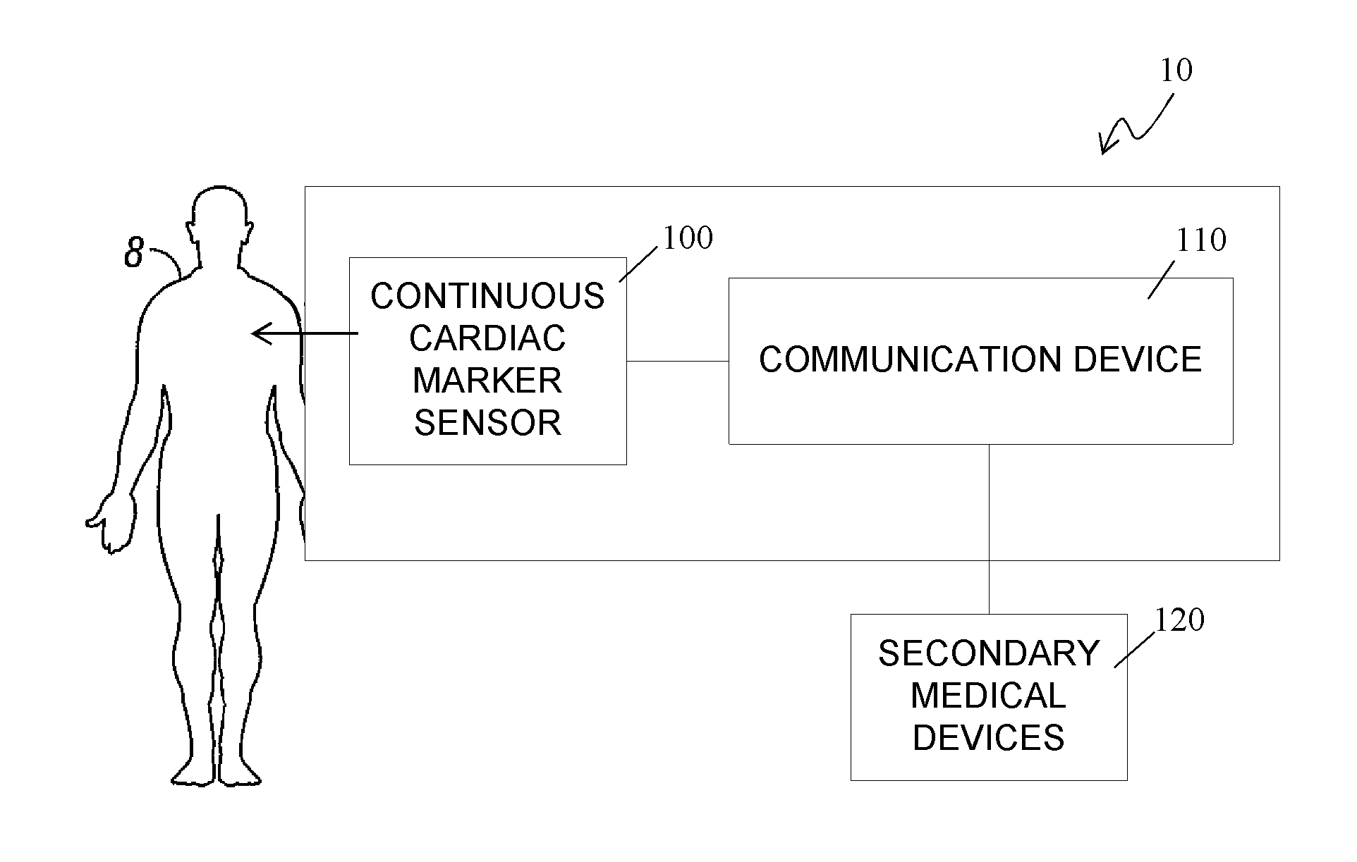
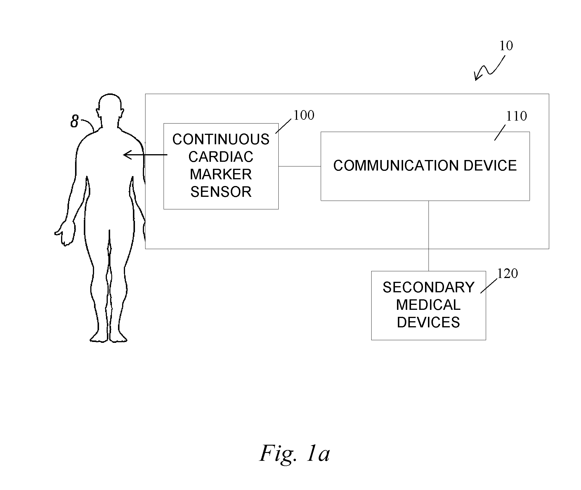
The patent describes a system for continuously detecting a cardiac marker in a person's body and using it to monitor their cardiac health. The system includes a sensor that measures the concentration of the marker in real-time and a communication device that processes the signal to obtain cardiac information. This information can be used to create a cardiac profile that indicates the person's cardiac status. The system can also provide alarms to alert medical professionals when the cardiac marker concentration reaches a certain level or there is a change in its concentration. The system can also include a vascular access device for insertion into the person's circulatory system or an extracorporeal blood circulation device. The system can also receive and process data from other medical devices, such as an electrocardiograph or a blood pressure monitor. Overall, the system allows for continuous monitoring of a person's cardiac health and can provide early detection of potential cardiac events.

Problems solved by technology

Diseases of the heart are a major cause of death & disability worldwide.
Given that heart diseases primarily affect an older population, the costs of medical care, for those afflicted with heart disease, are likely to increase.
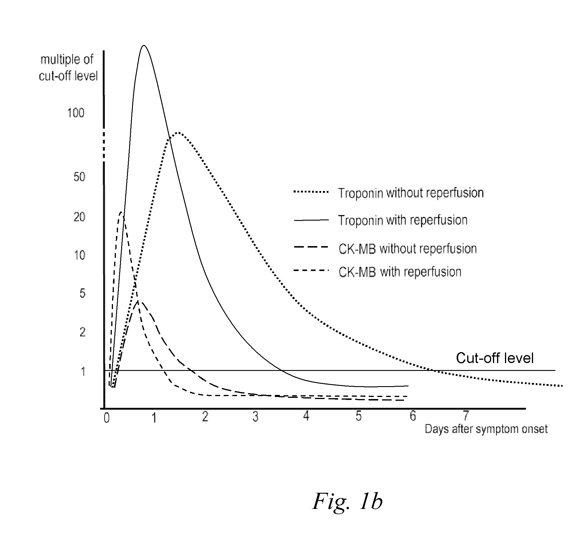
Obtaining the cardiac marker concentrations is currently a slow process that can take several hours, requiring blood collection and analysis in a clinical laboratory.

Method used


Image

  • Continuous cardiac marker sensor system
  • Continuous cardiac marker sensor system
  • Continuous cardiac marker sensor system

Examples


Embodiment Construction

[0042]The following description and examples illustrate a preferred embodiment of the present invention in detail. Those of skill in the art will recognize that there are numerous variations and modifications of this invention that are encompassed by its scope. Accordingly, the description of a preferred embodiment should not be deemed to limit the scope of the present invention.

DEFINITIONS

[0043]In order to facilitate an understanding of the preferred embodiments, a number of terms are defined below.

[0044]The term “A / D Converter” as used herein is a broad term, and is to be given its ordinary and customary meaning to a person of ordinary skill in the art (and it is not to be limited to a special or customized meaning), and refers without limitation to hardware and / or software that converts analog electrical signals into corresponding digital signals.

[0045]The term “alarm,” as used herein is a broad term and is to be given its ordinary and customary meaning to a person of ordinary sk...


PUM


Abstract

The present invention relates generally to systems and methods for continuous measurement of a cardiac marker in vivo. In some embodiments, the system includes a continuous sensor and a communication device. The continuous sensor is configured to continuously measure a concentration of a cardiac marker in vivo and to provide a signal associated therewith. The communication device includes a processor module configured to process the signal to obtain cardiac information, wherein the communication device is configured to output the cardiac information.

Description

CROSS-REFERENCE TO RELATED APPLICATIONS[0001]This application claims the benefit under 35 U.S.C. §119(e) of U.S. provisional application Ser. No. 61 / 024,841, filed Jan. 30, 2008, the disclosure of which is hereby expressly incorporated by reference in its entirety and is hereby expressly made a portion of this application.FIELD OF THE INVENTION[0002]The preferred embodiments relate generally to continuous detection and / or measurement of cardiac markers in vivo.BACKGROUND OF THE INVENTION[0003]Diseases of the heart are a major cause of death & disability worldwide. As of 2007, heart disease is the leading cause of death in the United States, England, and Wales, killing one person every 34 seconds in the United States alone. A variety of acute and chronic cardiac problems (e.g., ischemic cardiac injury, infarction, angina, inflammation of the heart and surrounding tissue due to infection, autoimmune disease, etc., arrhythmia, post-surgical problems, K+ and / or Ca2+ imbalances, and the ...

Claims


Application Information

Patent Timeline
Patent Type & Authority Applications(United States)
IPC IPC(8): A61B5/0205A61B5/145
CPCA61B5/0002A61B5/1427A61B5/7275A61B5/14546A61B5/412A61B5/14532A61B5/15003A61B5/150229A61B5/150389A61B5/150503A61B5/150809A61B5/150816A61B5/150824A61B5/15087A61B5/153A61B5/155A61B5/157
Inventor YANG, RICHARD C.MATSUBARA, BRADLEY SHIGETOBOOCK, ROBERT
Owner DEXCOM
Learn More