Detecting device for a cash drawer and a point of sales system

Active Publication Date: 2009-12-03
UNIVERSAL SCIENTIFIC INDUSTRIAL (SHANGHAI) CO LTD +1
View PDF1 Cites 4 Cited by
  • Summary
  • Abstract
  • Description
  • Claims
  • Application Information

AI Technical Summary

Benefits of technology

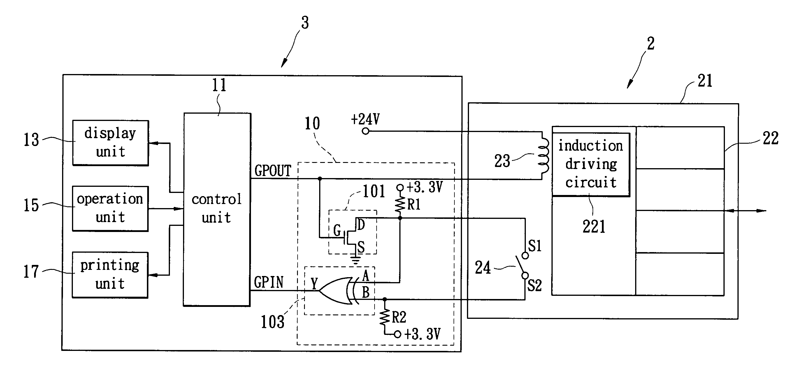
[0009]Another particular aspect of the present invention is to provide a detecting device for a cash drawer and a point of sales system. It uses a circuit design to confirm that the cash drawer is in the opened status when the cash drawer is stolen or moved. By utilizing this design, the user can monitor the real status of the cash drawer.
[0012]By utilizing the above device, when the cash drawer is stolen or moved, the detecting device for a cash drawer confirms that the cash drawer is in an opened status so that the control host exactly shows the real status of the cash drawer to lower the cash-loss risk.

Problems solved by technology

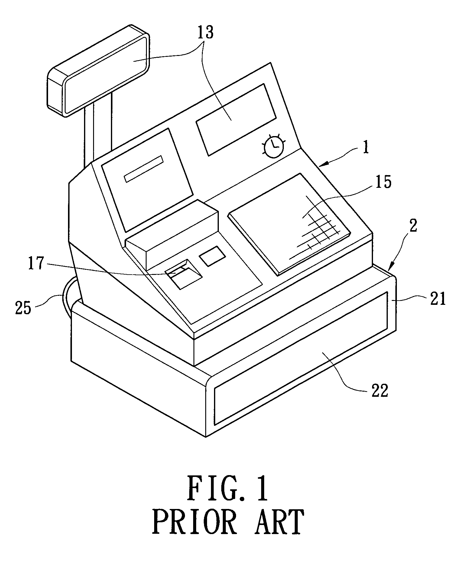
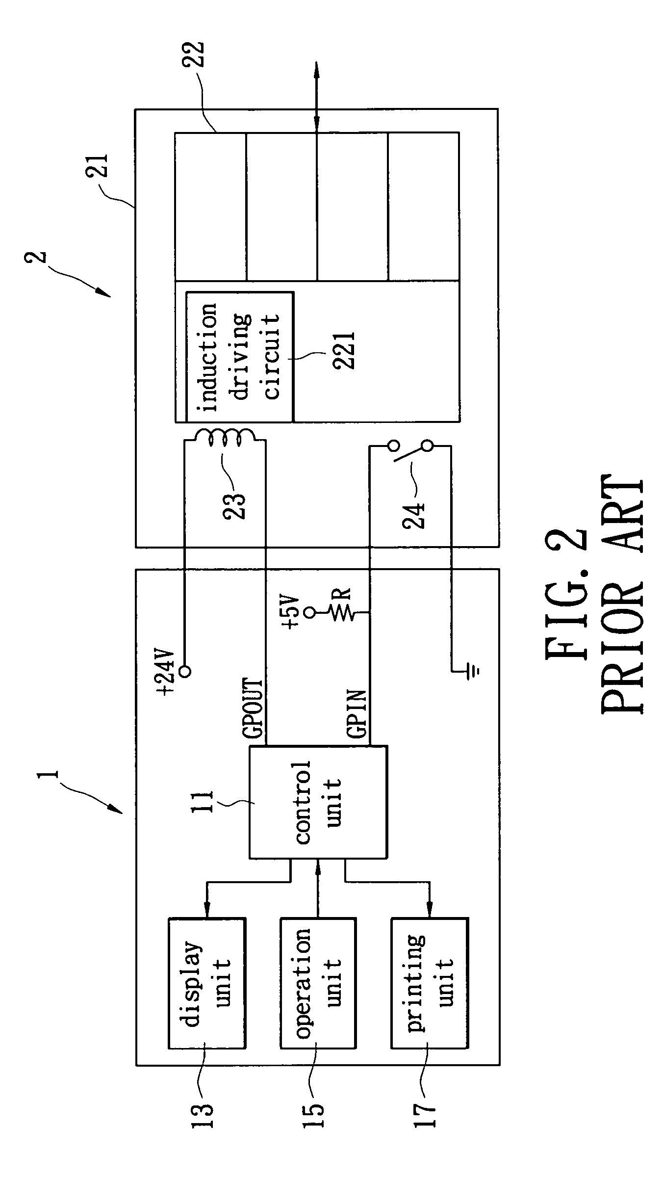
Therefore, the point of sales system of the prior art cannot show that status of the cash drawer 2 being stolen or moved.
It has a cash-loss risk for the owner of the store.

Method used


Image

  • Detecting device for a cash drawer and a point of sales system
  • Detecting device for a cash drawer and a point of sales system
  • Detecting device for a cash drawer and a point of sales system

Examples


first embodiment

[0020]Reference is made to FIG. 3, which shows a functional block diagram of the point of sales system of the present invention. The POS includes a control host 3 and a cash drawer 2. The control host 3 is used for controlling the automatic opening operation of the cash drawer 2 and performing the relative operations of the POS. A control unit 11 of the control host 3 is coupled with a display unit 13, an operation unit 15 and a printing unit 17, and controls the operations of the display unit 13, the operation unit 15 and the printing unit 17. For example, the display unit 13 displays a trade information (such as the payment for goods) and the status of the cash drawer (opened or closed). The operation unit 15 provides an interface for the user to perform the relative operations to the control host 3. The printing unit 17 prints the receipt. How to control the display unit 13, the operation unit 15 and the printing unit 17 by the control unit 11 is a known skill for the people in t...

second embodiment

[0032]Reference is made to FIG. 4, which shows a functional block diagram of the point of sales system of the present invention. The operation logic circuit 105 of the detecting device for a cash drawer 10′ in FIG. 4 is implemented by an XNOR gate. When a first input terminal A and a second input terminal B the XNOR gate 105 have the same logic voltage levels, an output terminal Y of the XNOR gate 105 outputs a logic high level (logic Hi). When the first input terminal A and the second input terminal B of the XNOR gate 105 have the different logic voltage levels, the output terminal Y of the XNOR gate 105 outputs a logic low level (logic Lo). The operation of the detecting device for a cash drawer 10′ in FIG. 4 is the same as FIG. 3, and is not repeated again.

[0033]The control unit 11 in FIG. 4 receives the output of the XNOR gate 105 via the pin GPIN. When the output terminal Y of the XNOR gate 105 is logic Hi, the control unit 11 treats the status of the cash drawer 2 as the opene...


PUM


Abstract

A detecting device for a cash drawer is used for detecting a status of the cash drawer. The detecting device includes an operation logic circuit and a switch element. The operation logic circuit has a first input terminal, a second input terminal and an output terminal. The first input terminal and the second input terminal are respectively coupled with a micro switch. The first input terminal and the second input terminal are respectively inputted with a high level voltage. When the first input terminal and the second input terminal have the same logic voltage levels, the operation logic circuit outputs a first logic level to the output terminal. When the first input terminal and the second input terminal have different logic voltage levels, the operation logic circuit outputs a second logic level to the output terminal. The switch element is coupled between an electromagnetic switch and the first input terminal.

Description

BACKGROUND OF THE INVENTION[0001]1. Field of the Invention[0002]The present invention relates to a detecting device. In particular, this invention relates to a detecting device that detects whether a cash drawer is opened or closed.[0003]2. Description of the Related Art[0004]In retail stores, usually electronic ways are used to manage the payment for goods, such as point of sales (POS) systems. FIG. 1 shows a typical point of sales system. The POS includes a control host 1, and a cash drawer 2. The control host 1 provides a lot of basic functions, such as inputting price, calculating the total payments for goods, printing the receipt, and displaying the payments for goods, etc. The control host 1 also controls the cash drawer 2 to be opened via an electronic way so that the cash can be put into the cash drawer 2 or take out from the cash drawer 2.[0005]The functional block of the point of sales system in FIG. 1 is shown in FIG. 2. In FIG. 2, the control host 1 controls a display un...

Claims


Application Information

Patent Timeline
IPC IPC(8): G06G1/12
CPCG06Q20/202G07G3/006G07G1/0027
Inventor CHIEN, YU-FENGWEI, YEN-YILIN, YI-MINGTSAI, MENG-YUAN
Owner UNIVERSAL SCIENTIFIC INDUSTRIAL (SHANGHAI) CO LTD
Why Eureka
Try Eureka