Method for Applying Electrical Conductor Patterns to a Target Component of Plastic

a technology of electrical conductors and target components, applied in the direction of printed circuit components, porous dielectrics, printed circuit dielectrics, etc., can solve the problems of retrospective application of conductor structures, complex installation processes, and inability to ensure the durability of the conductor structures required on the target component for the subsequent operation of the motor vehicle, etc., to achieve adequate flexibility, simple, quick and cost-effective

Inactive Publication Date: 2009-12-10
HIRSCHMANN CAR COMMUNICATION
View PDF6 Cites 0 Cited by
  • Summary
  • Abstract
  • Description
  • Claims
  • Application Information

AI Technical Summary

Benefits of technology

[0008]Overall either the introduction of a heated plastic melt or of the foaming plastic material offers great freedom with regard to the design and production costs of the target component on one hand, but the plastic material can also be selected depending on the end use of the target component on the other hand. Foaming plastic materials, for example, are preferred, if a savings of weight at the installation site of the target component is important, while target components that are made from a heated plastic melt are more stable due to the greater density of the finished target component.
[0009]A further development of the invention provides that the transfer medium is reshaped before or during the filling process. Since before the transfer medium is introduced into the mold part, its shape can deviate but does not necessarily do so, it is of advantage to reshape the transfer medium before or during the filling process, i.e. to conform it to the inside shape of the mold part that corresponds to the outside shape of the finished target component. This can be carried out, for example, mechanically, using vacuum, with the aid of an electrostatic charge in the mold part, or similar. The important part during the introduction of the transfer medium into the mold part, regardless of whether the transfer medium is reshaped before or during the filling process, or maintains its original shape, is that the transfer medium be fixed in the mold part such that after the production of the target component the transfer medium is on its outside surface, i.e. forms its outside surface at least partially, or even completely.
[0010]A further development of the invention provides that the entire target component is reshaped during or after the filling process. This means that the target component obtains its final shape from the shape of the mold part, or that the target component obtains its initial shape by filling the mold part with the plastic material. After removing the finished target component from the mold it is then plastically reshaped by a suitable method. Particularly, it is given its final shape by the effect of heat and pressure. To this end attention must be paid to the fact that the conductor structures are not damaged with this subsequent reshaping, in particular, that breaks are avoided.
[0011]In a further development of the invention the transfer medium is a film, which has the particular advantage that the conductor structures can be applied upon it in a simple, quick, and cost-effective manner, and which provides adequate flexibility during its introduction into the mold part.

Problems solved by technology

However, this method of retrospectively applying the conductor structures has disadvantages, since a complex adjustment process between the material of the conductor structure and the target material is necessary, and the durability of the conductor structures required on the target component for the subsequent operation of the motor vehicle is not ensured.
Furthermore, a complex installation process is required in a disadvantageous manner.
In addition, large problems exist with the retrospective application of the conductor structures to the target component, since it is usually complex, such as curved, bent, or such.
This results in the retrospective application of conductor structures, if it is possible at all, being very complex.

Method used


Image

  • Method for Applying Electrical Conductor Patterns to a Target Component of Plastic
  • Method for Applying Electrical Conductor Patterns to a Target Component of Plastic
  • Method for Applying Electrical Conductor Patterns to a Target Component of Plastic

Examples


Embodiment Construction

[0004]The object of the invention is therefore to provide a method of applying electric conductor structures to a plastic target component, which is simple to do and which avoids the disadvantages described above. Furthermore, a target component having electric conductor structures produced according to the method is to be provided.

[0005]This object is attained by the characteristics of patent claim 1.

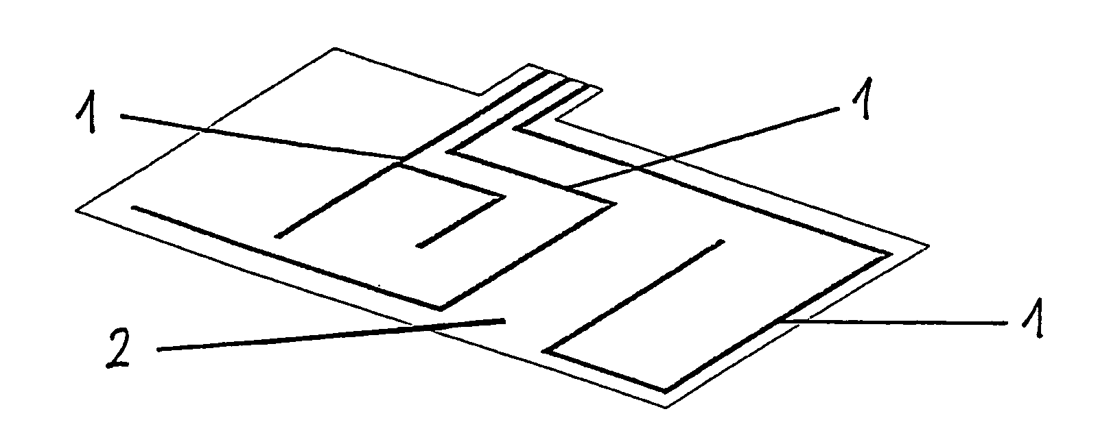
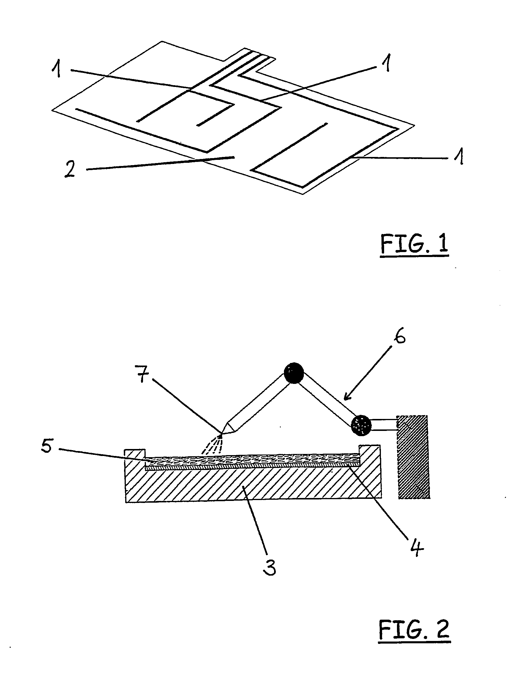
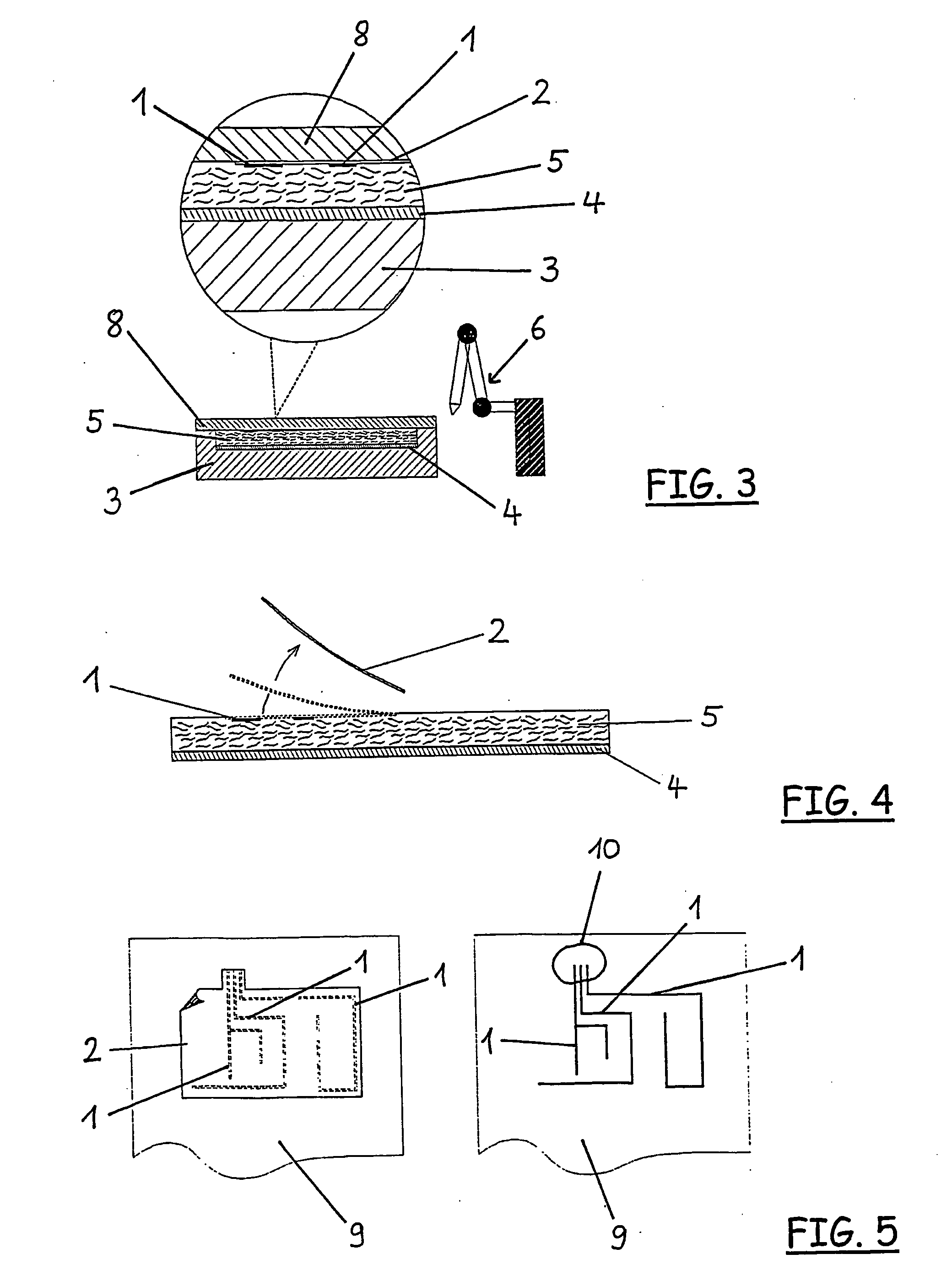
[0006]According to the invention a transfer medium, on which the conductor structures are mounted in a detachable manner, is introduced into a mold part (also called a mold), and the mold part is then filled with a plastic material, and after the filling process the finished target component is removed from the mold part. This method has the advantage that initially the conductor structures are applied to a transfer medium, and in a particular embodiment of the invention the transfer medium is a film made of plastic. The use of a transfer medium further has the advantage that it only h...


PUM

PropertyMeasurementUnit
electricaaaaaaaaaa
flexibleaaaaaaaaaa
pressureaaaaaaaaaa

Abstract

The invention relates to a method for applying electrical conductor patterns (1) to a target component (9) of plastic, it being provided according to the invention that a transfer medium on which the conductor patterns (1) are detachably arranged is placed in a mould part (3, 4) and the mould part (3, 4) is filled with a polymer material, the finished target component (9) being removed from the mould part (3, 4) after the filling.

Description

[0001]The invention relates to a method of applying electric conductor structures to a plastic target component according to the characteristics of the introductory clause of claim 1.PRIOR ART[0002]The production of target components made of plastic is known. It is known, for example with motor vehicles, to produce flat components, such as engine hoods, roofs, trunk lids, and the like from plastic for reasons of reducing weight. Mounted parts, such as fenders, doors, bumpers, and the like, of motor vehicles can be manufactured from plastic. In addition to reducing weight, these components made of plastic have the advantage over components of steel in that they cannot rust.[0003]In such motor-vehicle components, it is further known to also integrate or apply electrically conductive structures (conductors) that carry energy or signals. To this end, currently known methods for applying the conductor structures are used, wherein initially the target component is produced so that it has ...

Claims


Application Information

Patent Timeline
Patent Type & Authority Applications(United States)
IPC IPC(8): H05K3/20
CPCH05K1/0284H05K1/0393H05K3/0058H05K3/207Y10T29/49128H05K2201/0116H05K2201/09118H05K2203/1327H05K3/281
Inventor PFLETSCHINGER, MARKUSSCHWARZ, BERNDKRUGER, JANPETERSEN, INGMAR
Owner HIRSCHMANN CAR COMMUNICATION
Why Eureka
Try Eureka