Aircraft engine thrust reverser

a thrust reverser and aircraft engine technology, applied in the field of thrust reverser structure, can solve the problems of increasing weight, reducing the service life of the articulating activating linkage, increasing the cost, etc., and achieves the effects of reducing the deployment stroke, and saving weigh

Active Publication Date: 2009-12-10
SHORT BROTHERS
View PDF6 Cites 32 Cited by
  • Summary
  • Abstract
  • Description
  • Claims
  • Application Information

AI Technical Summary

Benefits of technology

[0009]In the present invention because the translating cowl moves along a path which is inclined to the power unit axis, the cowl cannot be in a single piece as it may be in the prior art structures. In the present invention the translating cowl may take the form of two translating cowl portions which may be orientated relative to each other diametrically opposite to one another. Whilst it is stated that there may be two cowl portions, it is feasible for there to be more than two cowl portions, however, it is believed that two cowl portions constitute the most efficient implementation of the present invention in terms of complexity, weight and thrust reversing efficiency.
[0010]The power unit may be provided with fixed structure on which the translating cowl portions may be moveably mounted, supported by slider rails. The slider rails may be orientated at an angle to an imaginary plane passing through the power unit axis. The angle at which the translating cowl portions move relative to the power unit axis may depend to a certain extent on the geometry of the engine nacelle itself. However, it is believed that an angle in the range from 5° to 20° may cover most geometries whilst a range of 5° to 12° is more preferred. Clearly, for any one design installation only one unique angle will be employed. The translating cowl portions and fixed structure may be provided with actuators therebetween, for example, to deploy and retract into the stowed position the cowl portions as required.
[0011]In a power unit installation where the power unit is mounted on a pylon under the wing, the fixed structure and slider rails mentioned hereinabove may be mounted in the 12 and 6 o'clock positions. Similarly, when the installation is a rear fuselage mounting then the fixed structure and slider rails may be at the 3 and 9 o'clock positions. Thus, the imaginary plane referred to above may be a substantially vertical plane in the former case and a substantially horizontal plane in the latter case.
[0012]In one embodiment of the present invention the power unit and thrust reverser structure may employ conventional cascades situated in the second fluid exit opening and exposed to fluid efflux when the translating cowl portions are deployed to their operative positions.
[0013]In a further modification of an embodiment employing cascades in the thrust reverser structure, the cascades may be canted or tilted relative to the engine axis giving a slight frusto-conical appearance to the cascades. The leading edge of the cascades (relative to the engine) may have a greater diameter than the trailing edge thereof. The benefit of canted cascades is that the trailing edge is moved further inwardly, away from the trajectory of movement of the translating cowl portions permitting a steeper angle of movement (towards the upper end of the range of 5° to 20° mentioned above) allowing a significantly reduced deployment stroke. The cascades may be canted at an angle of between 0.5° and 10° with a range of 2° to 7° being preferred. The actual angle will depend on the engine configuration in question and will inevitably be a compromise between several variables to provide an optimum overall configuration. A reduced deployment stroke has consequent benefits in weight saving and, where allied to steeper deployment trajectory, the possibility of greater optimisation of the aerodynamics of the by-pass fan duct leading to better fuel burn. This embodiment may be of greatest applicability to larger, more powerful engines where reduction of fuel burn will provide greater overall benefits than maximisation of reverse thrust per se which, in any event, will be entirely adequate.
[0014]In another embodiment of the present invention, conventional cascades may be dispensed with and alternative aerodynamic devices such as slots and slats, for example, used to secure the desired reverse thrust from the fluid efflux.

Problems solved by technology

Furthermore, the articulated activating linkage also adds weight, is prone to wear and requires maintenance all of which add cost.
However, in order to make this type of thrust reverser operate, the by-pass fan duct must have a more pronounced curvature or profile resulting in the surface area of the by-pass fan duct being increased which causes a small weight increase but, more importantly, causes pressure losses in the fan duct that may reduce forward thrust performance and consequently increase fuel burn.

Method used


Image

  • Aircraft engine thrust reverser
  • Aircraft engine thrust reverser
  • Aircraft engine thrust reverser

Examples


first embodiment

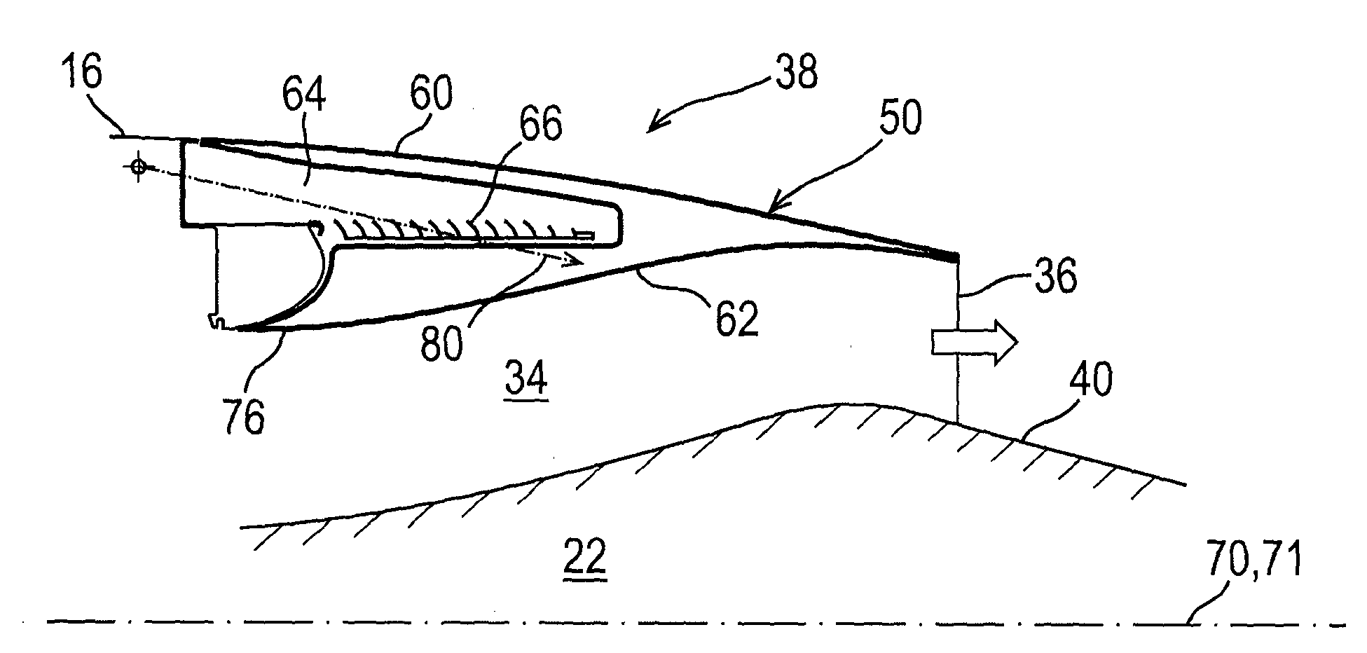
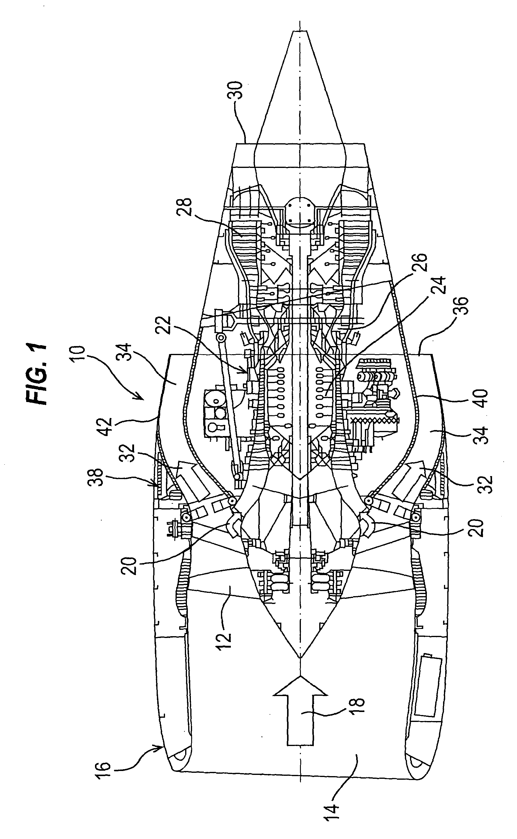
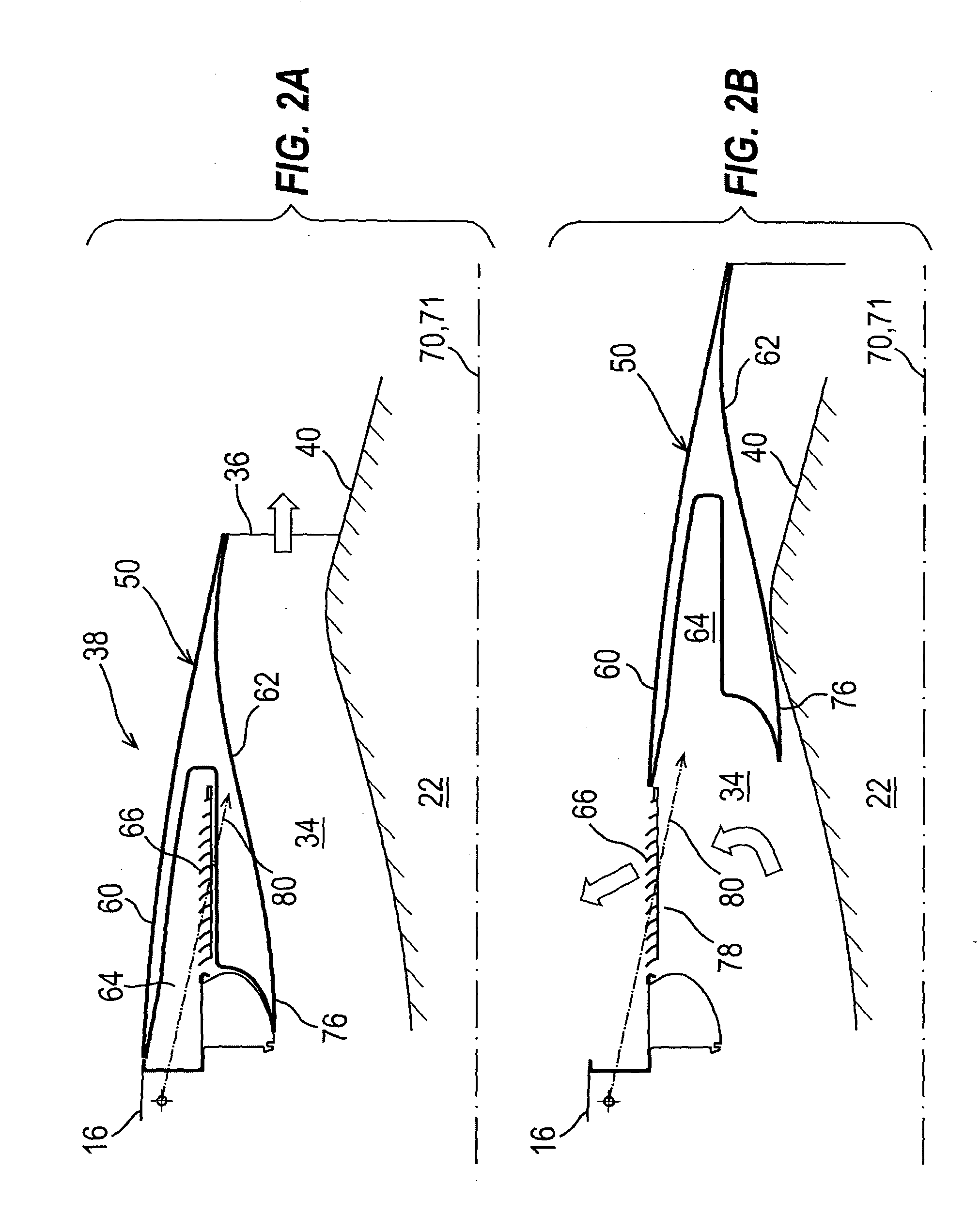
[0030]FIGS. 2A and 2B show a schematic cross section through a thrust reverser arrangement 38 according to the present invention; FIG. 2A being in the stowed (i.e. inoperative position) and 2B being in the deployed (i.e. operative position). Only the essential features of the invention are shown for the sake of clarity, and furthermore, only one side of the engine at a position circumferentially intermediate the location of slider rails on which the translating cowl portions (both of which to be described below) are mounted. FIGS. 2A and 2B are perhaps best viewed together with FIGS. 3A, 3B and FIG. 4 which show the thrust reverser arrangement of the present invention in the context of a whole engine 10 and a mounting pylon therefor.

[0031]The thrust reverser arrangement of the present invention comprises an inner by-pass fan duct cowling 40 surrounding the engine core 22 and an outer, translatable by-pass fan duct cowling portion 50. There is a matching by-pass fan duct cowling port...

third embodiment

[0036]the present invention is shown with reference to FIGS. 6A and 6B; 6A showing the thrust reverser arrangement in the stowed position and 6B in the deployed position. The basic structure of the reverse thrust arrangement in this embodiment is essentially the same as that described with reference to FIG. 2. However, in this embodiment, the reverse air flow assisting cascades 66 are replaced by a slot 100 arrangement defined by slats 102. The shape of the cavity 64 is so formed as to generate suitable flow and back pressure characteristics to assist air flow out of the second gaseous fluid exit opening 78, the slats 102 assisting the air flow to adhere to a nose portion 106 of the fixed cowl 16 to prevent flow separation and maximise reverse thrust air flow 108. The principles relating to control of air flow in this embodiment are fully described in EP-A-1 515 035 of common ownership herewith.

[0037]A fourth embodiment of the present invention is shown with reference to FIG. 7. In ...


PUM


Abstract

A power unit for providing propulsive thrust includes an efflux duct defining a first fluid flow path along which gaseous fluid travels for discharge from a first fluid exit opening to provide propulsive thrust. The power unit also has a thrust reversing structure which, when in a deployed position, redirects the flow of gaseous fluid along a second fluid flow path to discharge from a second fluid exit opening to provide reverse thrust. The thrust reversing structure includes longitudinally translating cowl portions, which are moveable from a stowed position to the deployed position where the translating cowl portions block a major portion of the first fluid exit opening to cause gaseous fluid to efflux from the second fluid exit opening. The translating cowl portions move in a generally longitudinal direction towards the deployed position along a path which is inclined to the power unit axis.

Description

FIELD OF THE INVENTION[0001]The present invention relates to a thrust reverser structure for an aircraft engine and to an engine having that thrust reverser structure.BACKGROUND[0002]Thrust reversers for aircraft engines, particularly gas turbine engines, are well known and take many and varied forms.[0003]One form of thrust reverser structure when used on a gas turbine engine having a by-pass fan and by-pass fan duct utilises so-called blocker doors which are activated by a cowl portion which translates rearwardly in a direction parallel to the engine axis and activates the blocker doors by means of an articulated linkage to substantially block the by-pass duct to propulsive fluid flow and redirect that fluid flow through a second outlet having flow directing cascades to provide reverse thrust to slow an aircraft when landing, for example. Whilst the by-pass fan duct may be contoured to optimise fluid flow therethrough when in normal propulsive mode to provide forward thrust, the b...

Claims


Application Information

Patent Timeline
Patent Type & Authority Applications(United States)
IPC IPC(8): F02K3/02
CPCF02K1/72F05D2250/314Y02T50/671Y02T50/60
Inventor HATRICK, MICHAEL JOHN
Owner SHORT BROTHERS
Why Eureka
Try Eureka