Tool, Sensor, and Device for a Wall Non-Distructive Control

a non-distructive control and wall technology, applied in the direction of material solid analysis using sonic/ultrasonic/infrasonic waves, measurement devices, etc., can solve the problems of unsuitable and current techniques for thoroughly scanning areas of several tens to several thousands of square meters, unfavorable, and inability to move the probe several million times

Inactive Publication Date: 2009-12-10
ROBOPLANET
View PDF14 Cites 84 Cited by
  • Summary
  • Abstract
  • Description
  • Claims
  • Application Information

AI Technical Summary

Benefits of technology

[0015]An object of the present invention is to remedy drawbacks that are inherent in the state of the art by proposing a tool, a sensor, and apparatus for non-destructive inspection making it possible to simultaneously move and apply the sensor against the wall or the structure for inspection, and to do so over large wall areas and large industrial structures such as ships, for example.
[0018]Each sensor is thus pressed individually against the wall with two degrees of freedom thereagainst, thus enabling it to be moved over the wall.
[0020]The tool enables various of the sensors to be pressed against a three-dimensional wall that may have any curvature. The support allows the sensors to follow the curvature of the wall and accommodate the differences in the heights of the sensors above a theoretical plane of the tool, where said differences are due to the differences in the height of the wall relative to said theoretical plane.
[0023]In one embodiment, the unit or tool has magnets and the robot has magnetized wheels serving to hold the tool pressed against the structure, providing the structure can attract a magnet as is the case for the steel of the hulls of ships, otherwise the unit and / or the robot includes a peripheral skirt and suction apparatus for removing the air between the unit and the structure by suction. A preferred disposition for the magnets comprises making the cases for the sensors out of magnetized material. These dispositions present the advantage of the sensors being pressed spontaneously by their own magnetization against the structure, with magnetic force replacing the application force applied by a human operator.

Problems solved by technology

Unfortunately, current techniques are unsuitable for thoroughly scanning areas of several tens to several thousands of square meters (m2) in large industrial structures, such as the hulls of ships, for example.
In order to inspect very large structures exhaustively at a regular sampling pitch in two dimensions of a few centimeters by a few centimeters, the operator would need to move the probe several million times, which is not possible.
Present-day inspections can thus be very sporadic: large areas remain unscanned and a statistical risk is taken based on the assumption that the structure does not present any defect between two spaced-apart measurement points.
Furthermore, the work undertaken by the operator is difficult because it is often necessary to work elevated on scaffolding or suspended in the air by cords, or to dive under the hull of a ship, and present measurement devices do not make this work any easier as it is necessary to hold the probe in position while adjusting and observing the display on the device.
Inspections carried out using present means are therefore lengthy and difficult.
In addition, in the present technique, the measurement points are poorly identified in three dimensions: for example operators apply chalk marks on the points where they have applied the probe and then photograph those marks.
However, such photographs are not sufficient for preparing a map of the structure: while they give approximate positions for the locations where measurements were performed, they do not enable those positions to be accurately quantified in three dimensions.
These devices are thus not self-contained and the repeated displacement of the support point or rail constitutes a handicap when the area for inspection is very large.
In practice, the measurement system is difficult to use for performing measurements on three-dimensional walls of large size.
Thus, in practice, such a measurement system is difficult to automate with a plurality of sensors and can be operated only by a human operator carrying, moving, and manually applying a single sensor against the wall, as is described in that document.
This measurement system thus presents the above-described drawbacks of manual systems in which it is the human operator who holds the measurement sensor against the wall.

Method used


Image

  • Tool, Sensor, and Device for a Wall Non-Distructive Control
  • Tool, Sensor, and Device for a Wall Non-Distructive Control
  • Tool, Sensor, and Device for a Wall Non-Distructive Control

Examples


Embodiment Construction

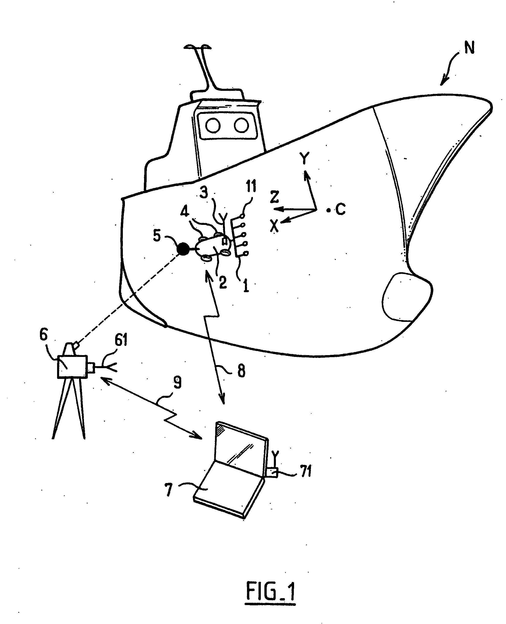
[0046]A method of taking measurements that is performed by using a non-destructive inspection apparatus of the invention is described below and shown in the figures for the example of the steel hull of a ship.

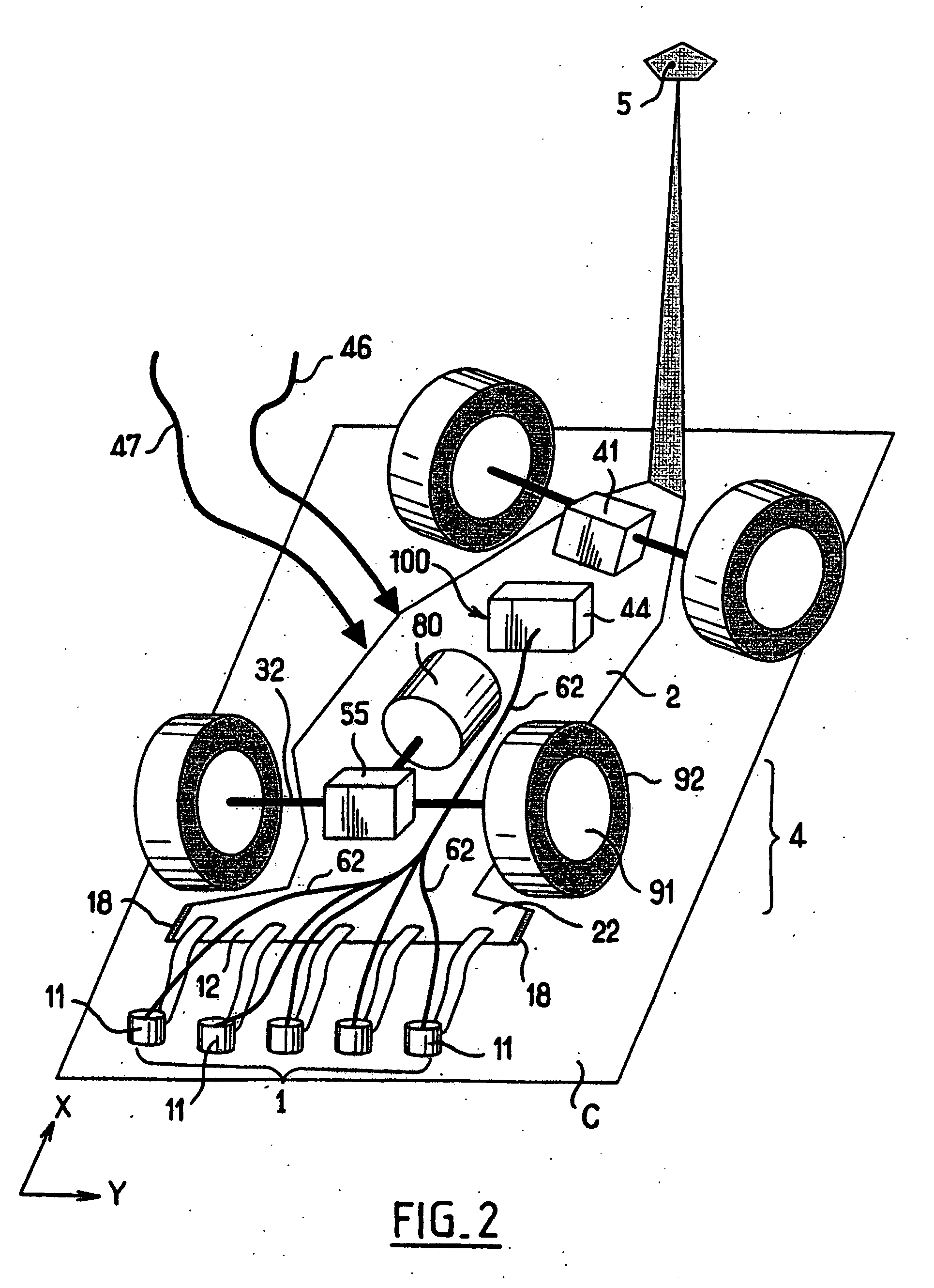
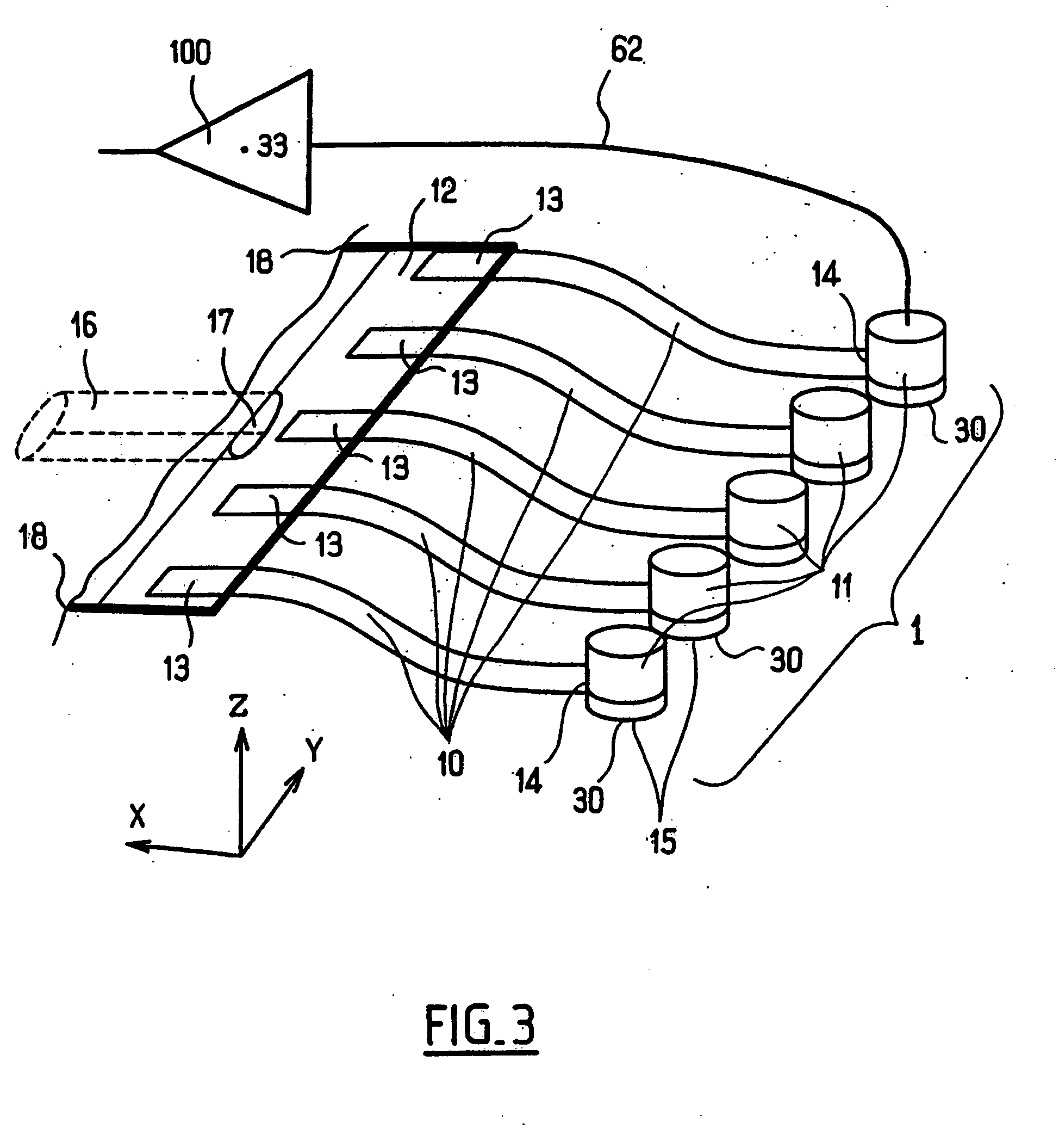
[0047]In FIG. 1, the apparatus comprises a measurement unit or inspection tool 1 comprising a plurality of measurement sensors 11 that is moved, e.g., towed, by a robot 2 rolling on the hull C of the ship N in a lengthwise direction X and a widthwise direction Y, adhering to the hull by means of magnetized wheels 4, the direction Z oriented upwards relative to the hull C being perpendicular to the directions X and Y. By way of example, the sensors 11 are sensors for measuring local thickness, using interface circuits and an onboard computer 44, as described below with reference to FIG. 8, to generate thickness data that is referred to below as measurement data.

[0048]The robot 2 and / or the inspection tool 1 include a measurement data transmitter or transmission means 3 for trans...


PUM

PropertyMeasurementUnit
distanceaaaaaaaaaa
degree of freedomaaaaaaaaaa
widthaaaaaaaaaa

Abstract

The invention relates to a tool for non-destructive inspection of a three-dimensional wall, the tool including a plurality of juxtaposed non-destructive inspection sensors. The sensors are mounted on a support for moving the set of sensors in common relative to the wall. The support is deformable for each of the sensors so that the sensors are movable relative to one another. Also provided are a constraint element for constraining the application face of each sensor to press individually against the wall and a sliding element for causing the application face of each sensor to slide against the wall.

Description

BACKGROUND OF THE INVENTION[0001]1. Field of the Invention[0002]The present invention relates to the non-destructive inspection of the state of large industrial structures such as, for example, ships, pipelines, or storage tanks.[0003]2. Discussion of Related Art[0004]Non-destructive inspection is traditionally performed by an operator manually applying a measurement probe against or close to the surface of the structure for inspection. The probe then emits acoustic, ultrasound, or electromagnetic pulses which propagate in the material of the structure and which are partially reflected by any fractures, welds, corrosion blemishes, walls, or non-uniformities. The probe receives these reflected signals and converts them into electrical signals that are displayed by an electronic device. The operator makes use of the display, e.g., for measuring the thickness of the material at the point where the probe is placed.[0005]Unfortunately, current techniques are unsuitable for thoroughly sca...

Claims


Application Information

Patent Timeline
Patent Type & Authority Applications(United States)
IPC IPC(8): G01N29/265
CPCG01N29/225G01N2291/106G01N29/28G01N29/265
Inventor BRUSSIEUX, MARC
Owner ROBOPLANET
Why Eureka
Try Eureka