Breather device for engine

a technology for breathers and engines, which is applied in the direction of combustion engines, machines/engines, pressure lubrication, etc., can solve the problems of inhibiting the closing operation of elastic valve plates and the inability to keep the crank chamber under negative pressur

Active Publication Date: 2009-12-10
HONDA MOTOR CO LTD
View PDF15 Cites 17 Cited by
  • Summary
  • Abstract
  • Description
  • Claims
  • Application Information

AI Technical Summary

Benefits of technology

[0007]The present invention has been made in consideration of such circumstances, and has an objective to provide a breather device for engine in which an el

Problems solved by technology

Such oil mist adherence possibly causes the elastic valve plate to stick to the stopper plate when the elastic valve plate is brought to an opening limit position in which the elastic valve plate abuts against the s

Method used


Image

  • Breather device for engine
  • Breather device for engine
  • Breather device for engine

Examples


Embodiment Construction

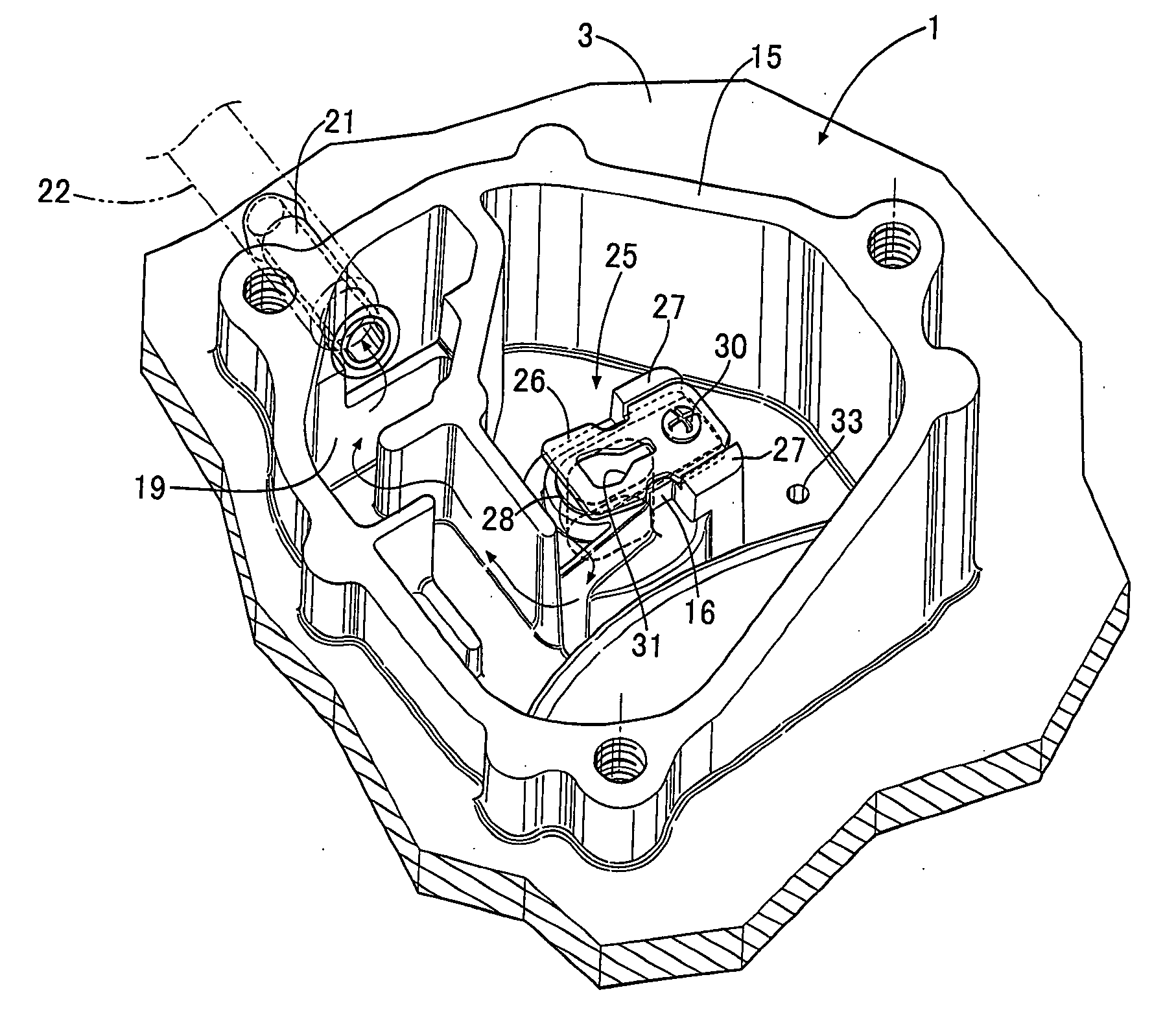
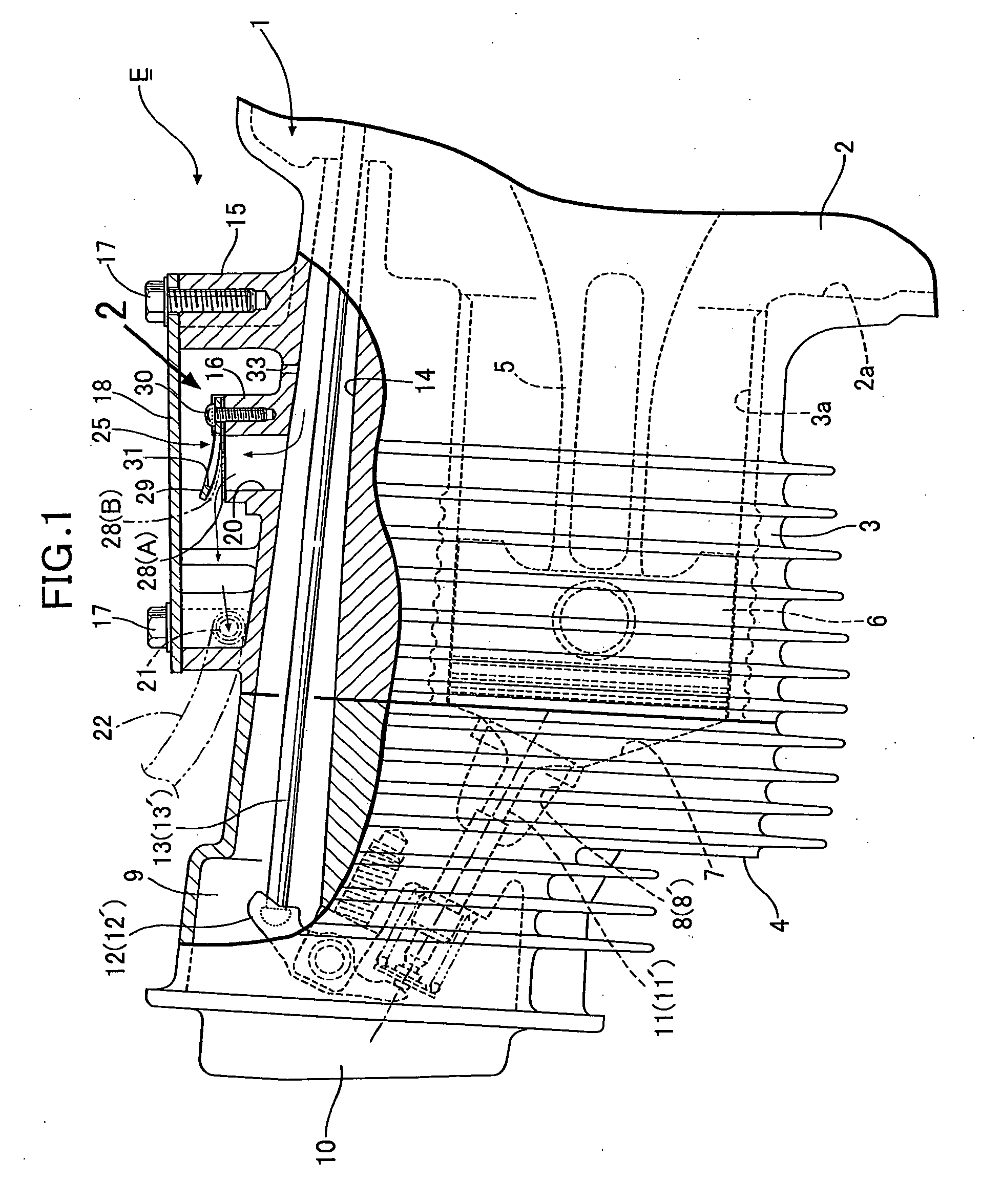
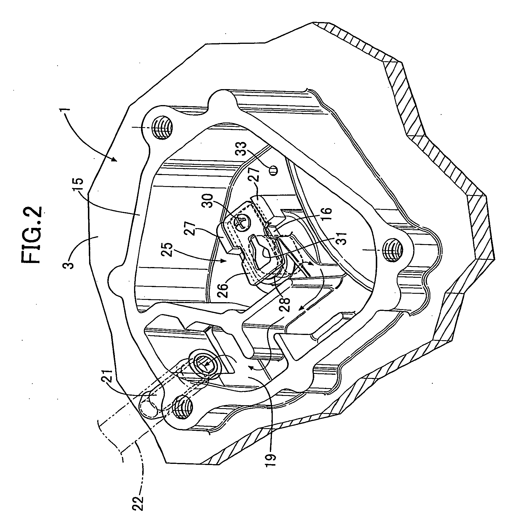
[0019]An embodiment of the present invention will be explained below with reference to FIG. 1 to 3.

[0020]In FIG. 1, reference numeral E denotes a general-purpose engine. An engine body 1 of the general-purpose engine E is formed of a crankcase 2 supporting a crankshaft (not shown), a cylinder block 3 provided to one side of the crankshaft 2 in a continuous manner and placed substantially horizontally, and a cylinder head 4 joined to an end face of the cylinder block 3. The cylinder block 3 has a cylinder bore 3a into which a piston 6 is slidably fitted. The piston 6 is connected to the crankshaft via a connecting rod 5. A combustion chamber 7 and intake and exhaust ports 8 and 8′ are formed in the cylinder head 4. The combustion chamber 7 is in communication with the cylinder bore 3a, and the intake and exhaust ports 8 and 8′ are open to the combustion chamber 7. Moreover, intake and exhaust valves 11 and 11′ are attached to the cylinder head 4 to open and close the intake and exhau...


PUM


Abstract

In a breather device for engine, in which an inlet of a breather chamber communicates with a crank chamber through a reed valve, the reed valve being formed of: a fixed stopper plate arranged so as to be opposed to a valve seat formed on an end face of the inlet facing the breather chamber; and an elastic valve plate fixed at one end thereof to the stopper plate and capable of bending elastically to change its position from a closed position in which the elastic valve plate closes the inlet by seating on the valve seat to an opening limit position in which the elastic valve plate opens the inlet and abuts against the stopper plate, the stopper plate is provided at a center part thereof with an oil discharge hole through which oil present between the elastic valve plate and the stopper plate is pushed out when the elastic valve plate is pushed toward the opening limit position in which the elastic valve plate abuts against the stopper plate by pressure in the crank chamber. Accordingly, it is possible to prevent the elastic valve plate from sticking to the stopper plate even if oil mist adheres to the elastic valve plate or the stopper plate of the reed valve.

Description

CROSS-REFERENCE TO RELATED APPLICATIONS[0001]The present invention claims priority under 35 USC §119 based on Japanese patent application No. 2008-147722 filed Jun. 5, 2008. The subject matter of this priority document is incorporated by reference herein.BACKGROUND OF THE INVENTION[0002]1. Field of the Invention[0003]The present invention relates to an improvement of a breather device for engine, in which an inlet of a breather chamber communicates with a crank chamber of an engine through a reed valve that allows gas to flow only in one direction from the crank chamber side to the breather chamber side, the reed valve being formed of: a valve seat formed on an end face of the inlet facing the breather chamber; a fixed stopper plate arranged so as to be opposed to and distanced form the valve seat; and an elastic valve plate fixed at one end thereof to the stopper plate and capable of bending elastically to change its position from a closed position to an opening limit position, the...

Claims


Application Information

Patent Timeline
IPC IPC(8): F02B25/06F01M1/04
CPCF01M13/022F01M2013/0488F01M2013/0461F01M13/04
Inventor OGAWA, KAZUHISAHASEBE, HIROAKI
Owner HONDA MOTOR CO LTD
Why Eureka
Try Eureka