Heat and moisture exchanger, heat and moisture exchanging device, and mask

a technology of heat exchanger and airway, which is applied in the direction of breathing mask, breathing protection, other medical devices, etc., can solve the problems of suffocation of the airway, poor airway of the patient, and poor airway of the passive type when compared to the active typ

Active Publication Date: 2009-12-10
FURREX
View PDF9 Cites 15 Cited by
  • Summary
  • Abstract
  • Description
  • Claims
  • Application Information

AI Technical Summary

Benefits of technology

[0027]An object of the present invention is to provide a heat and moisture exchanger capable of a

Problems solved by technology

However, it is a fact that as far as performance in warming and humidifying is concerned, the passive types are generally inferior when compared to the active ones.
The above conventional HMEs, however, have the following problems.
One problem is that an airway of a patient tends to dry because of poor warming and humidifying capability and a fatal complication may be resulted by suffocation of the airway due to hardening of secretions.
Another problem is clogging caused by condensed water accumulated in the HME.
However, those metal type HMEs have several problems such as its bulkiness and

Method used


Image

  • Heat and moisture exchanger, heat and moisture exchanging device, and mask
  • Heat and moisture exchanger, heat and moisture exchanging device, and mask
  • Heat and moisture exchanger, heat and moisture exchanging device, and mask

Examples


embodiment 1

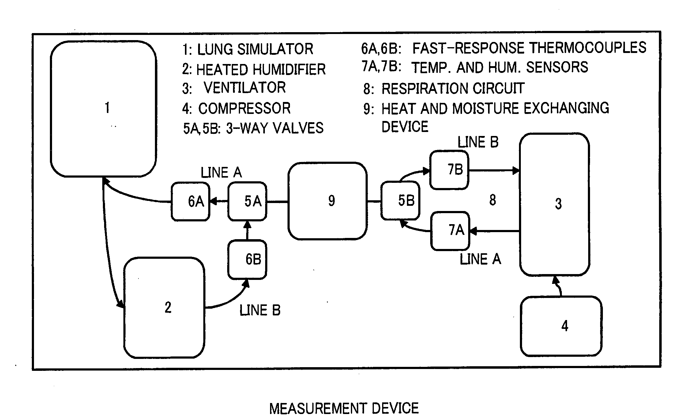
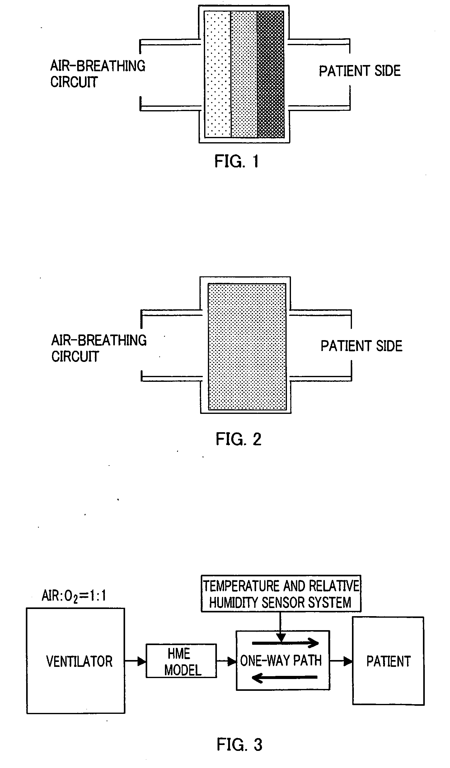
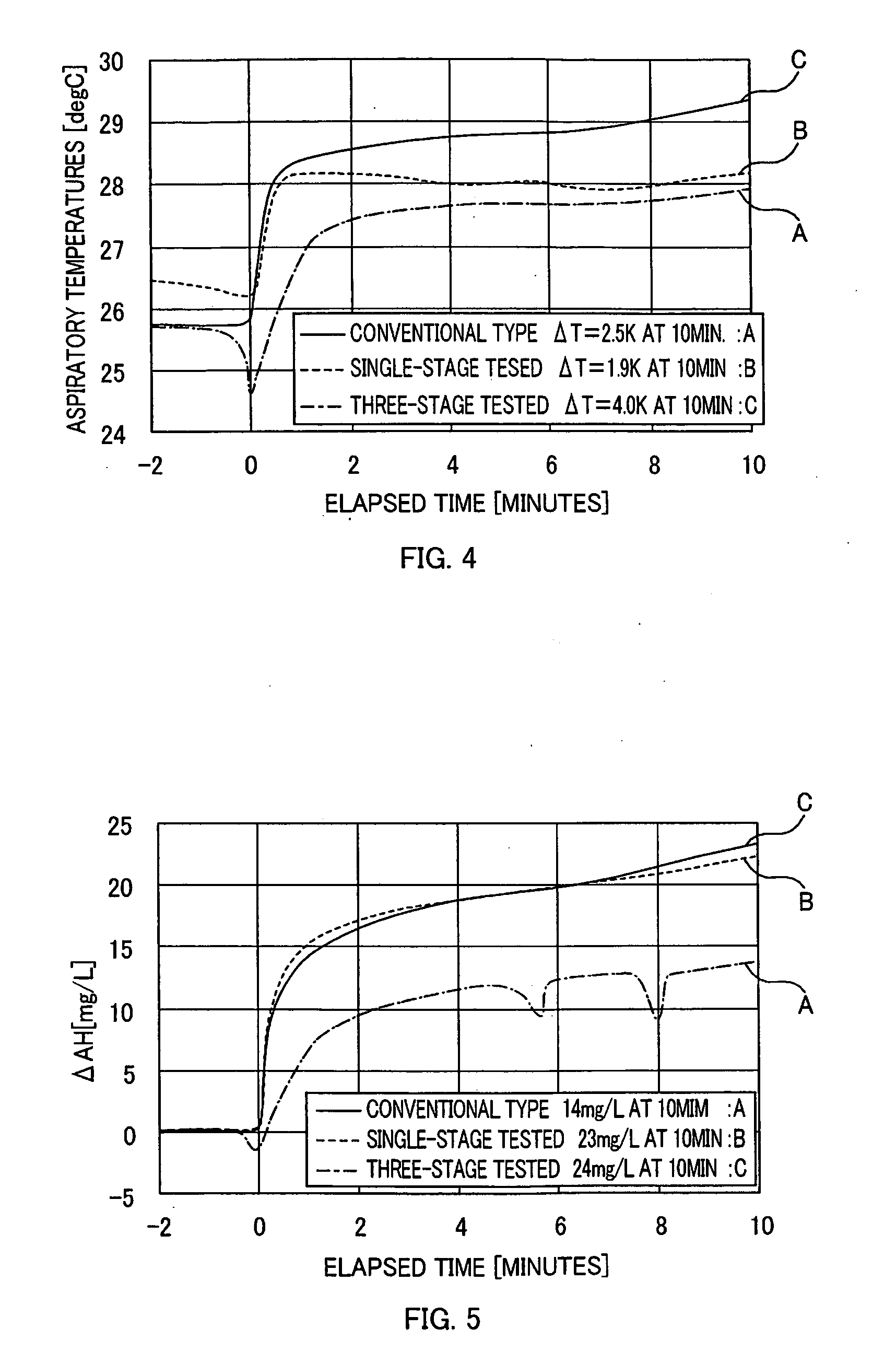
[0060]As shown in FIGS. 1 and 6, a three-staged HME 10 comprises a heat storage carrier material (thermal storage unit) 14 and a housing 12 containing the same. The heat storage carrier material 14 further includes three heat storage elements 14a-14c, each being made of polyurethane with a different density. Each element 14a-14c may include / consist of cellulose. The elements 14a-14c are arranged in series along a gas flow direction, as the density decreases from the patient side, so as to obtain a three-staged HME 10 according to one embodiment of the present invention. A density of each element 14a-14c is arranged 80, 57, and 30 kg / m3 in descending order. To demonstrate its effectiveness, a test sample, a conventional single-staged HME 10 with a heat storage carrier material 14 of no density difference in FIG. 2 is evaluated for comparison of performance. The density of the heat storage carrier material 14 of the test sample amounts to 57 kg / m3, an averaged density of the above thr...

embodiment 2

[0068]A description is given below of aspects of the present invention according to another embodiment. As an application of the respiratory heat and moisture exchanger, the description proceeds using as an example a heat and moisture exchanging device and a mask.

[0069]As described above, when regenerating heat from exhaled air into the air to be inhaled by a patient that is sent from an artificial respirator or an anesthetic device to the patient through a heat and moisture exchanging device, further increasing the heat regeneration rate of the respiratory heat and moisture regenerator disposed within the heat and moisture exchanging device is a problem to be solved.

[0070]In addition, with respect to the heat and moisture exchanging device described above, it is recognized that, as the capacity to add heat improves, there is room for improvement also in the capacity to add moisture. Further, with the structure proposed above, it has been confirmed that there is an unevenness in the...

example 2

[0089]Next, two types of samples, Sample A and Sample B, were prepared in order to compare the heating and humidifying characteristics of a heat and moisture exchanging device provided with a respiratory heat and moisture exchanger according to a second embodiment of the present invention.

Sample A

[0090]Using a heat storage carrier material made of polyurethane foam formed into a substantially cylindrical shape having a nominal volume of 52.3 cm3, the carrier is divided into four layers, a first layer through a fourth layer, in which the density varies, in order from the patient side, from 30 to 55 to 55 to 70 kg / m3, with each layer having a thickness of 5.5 mm. In other words, the heat storage carrier material of Sample A is given a density gradient such that the density increases from the patient side toward the circuit side. The heat storage carrier material is held inside a container provided with openings at two places through which simulated respiratory air passes, and connecte...


PUM


Abstract

A heat and moisture exchanger configured to be located between a respiratory system of a patient and an anesthesia circuit connected to an anesthesia apparatus, or a respiratory circuit connected to a respirator for maintaining a temperature and humidity of an aspired gas required to a patient under anesthesia or artificial respiration comprises a heat storage carrier material, and a moisture absorption and release material added to the heat storage carrier material. In the heat and moisture exchanger, at least one of density of the heat storage carrier material, number of cells of the heat storage carrier material, and an added amount of the moisture absorption and release material in the heat storage carrier material is set to decrease from the patient side to the side of the anesthesia apparatus or the respirator, along a flow direction of a respiratory gas in the heat storage carrier material.

Description

CROSS-REFERENCE TO RELATED APPLICATIONS[0001]The present application is a continuation-in-part of International Application PCT / JP2007 / 070208 designating the U.S., with an international filing date of Oct. 10, 2007, claiming a priority from U.S. provisional patent application No. 60 / 850,698 filed on Oct. 10, 2006, the contents of which are herein incorporated by reference, and of International Application PCT / JP2009 / 070208 designating the U.S., with an international filing date of Mar. 9, 2009, claiming priorities from U.S. provisional patent applications No. 61 / 043,474 filed on Apr. 9, 2008 and No. 61 / 105,929 filed on Oct. 16, 2008, the contents of which are herein incorporated by reference.BACKGROUND ART[0002]1. Technical Field[0003]The present invention relates to a respiratory heat and moisture exchanger, heat and moisture exchanging device, and mask, and more particularly, to a respiratory heat and moisture exchanger, heat and moisture exchanging device, and mask for appropriat...

Claims


Application Information

Patent Timeline
IPC IPC(8): A61M16/16A61M16/06
CPCA61M16/1045A61M16/161A61M2209/02A61M2205/3368
Inventor OHMURA, AKITOEGUCHI, KUNIHISAMIYAJI, TETSUYAGOTO, KATSUYOSHI
Owner FURREX
Why Eureka
Try Eureka