Azimuth detecting apparatus and radar apparatus

a radar and azimuth detection technology, applied in the direction of antennas, multi-channel direction-finding systems using radio waves, instruments, etc., can solve the problems of increasing the manufacturing cost, difficult detection of radar apparatuses, and general limited space in the vehicle for installation of radar apparatuses, so as to accurately detect azimuth

Inactive Publication Date: 2009-12-10
DENSO CORP
View PDF3 Cites 15 Cited by
  • Summary
  • Abstract
  • Description
  • Claims
  • Application Information

AI Technical Summary

Benefits of technology

[0018]It is preferable for the above azimuth detecting apparatus to be used in a motor vehicle. In this case, the azimuth detecting apparatus would be able to de

Problems solved by technology

As a result, it is difficult for the radar apparatus to detect, in an early stage, another vehicle cutting in front of the vehicle from the side.
However, with the above configuration, the receiving antenna would be enlarged, r

Method used


Image

  • Azimuth detecting apparatus and radar apparatus
  • Azimuth detecting apparatus and radar apparatus
  • Azimuth detecting apparatus and radar apparatus

Examples


Embodiment Construction

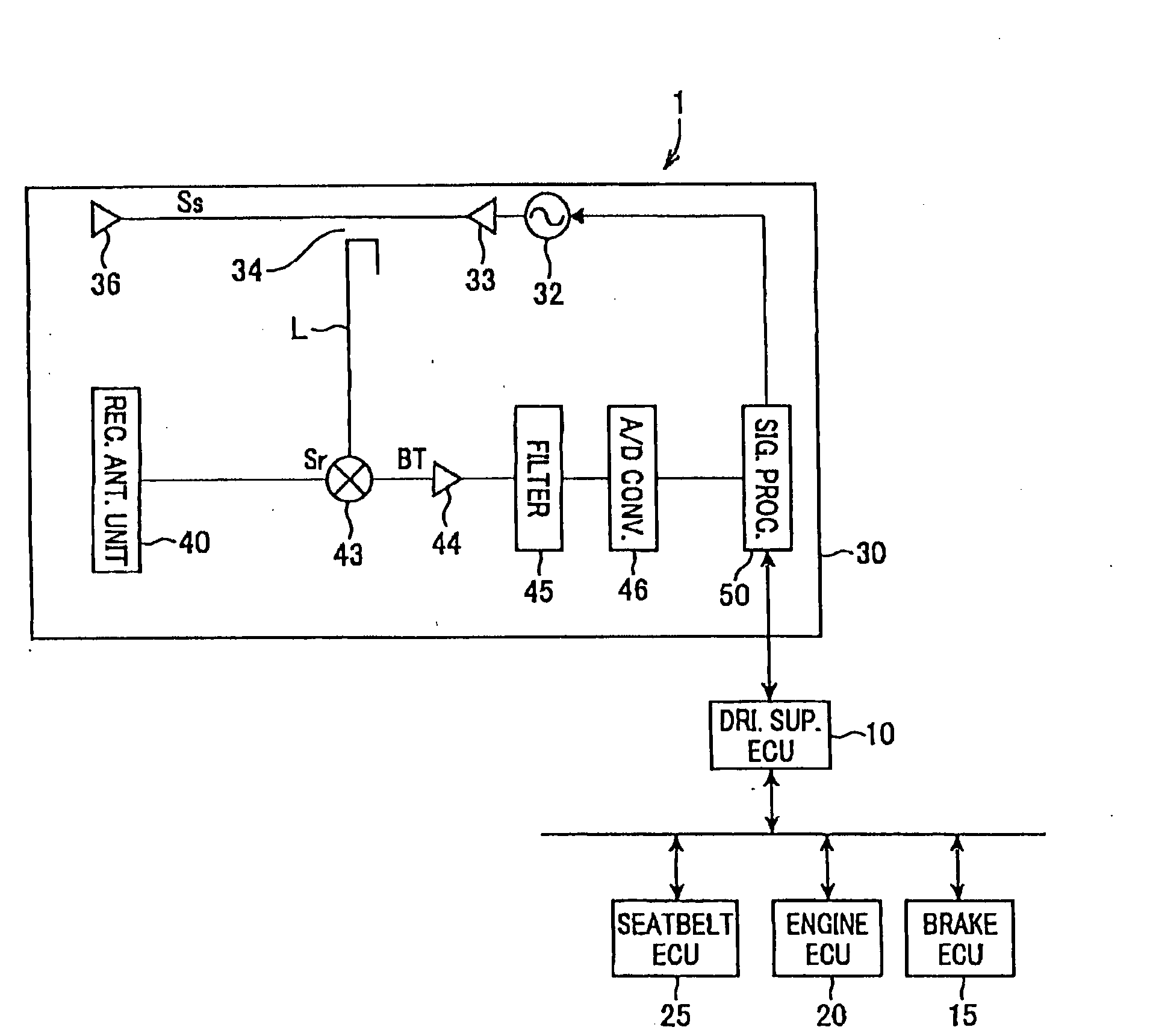
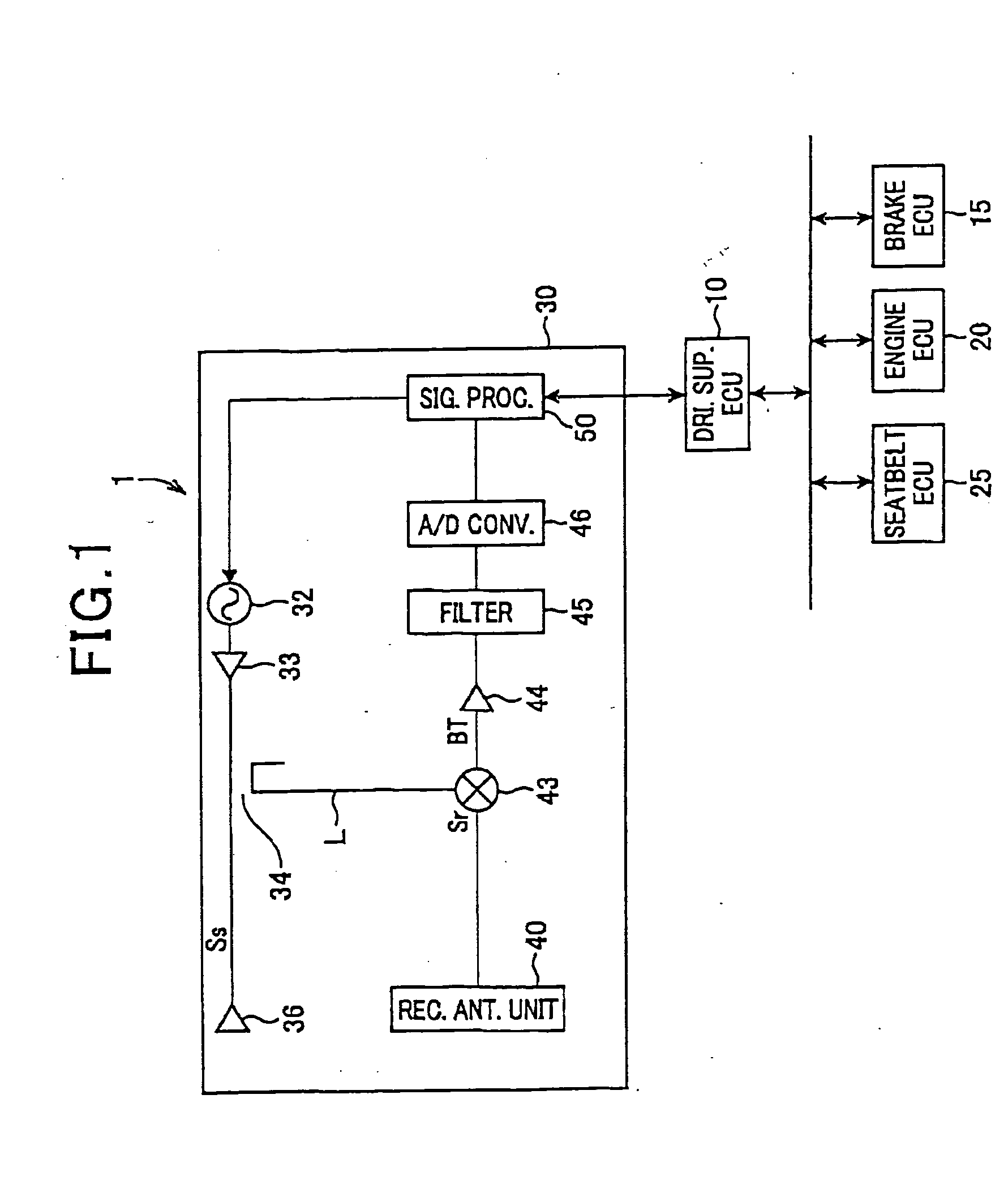
[0033]FIG. 1 shows the overall configuration of a driving support system 1 which includes a radar sensor 30 according to a preferred embodiment of the invention.

[0034]The driving support system 1 is installed in a front portion of a motor vehicle. The radar sensor 30, which detects objects present in front of the vehicle, is connected to a driving support ECU (Electronic Control Unit) 10. The driving support ECU 10 is further connected, via a LAN communication bus, to each of a brake ECU 15, an engine ECU 20, and a seatbelt ECU 25.

[0035]Each of the ECUs 10, 15, 20, and 25 is configured mainly with a microcomputer which includes a CPU, a ROM, and a RAM.

[0036]Each of the ECUs 10, 15, 20, and 25 also includes a bus controller for performing communication via the LAN communication bus.

[0037]The radar sensor 30 is configured as an EHF Extremely High Frequency) radar apparatus of FMCW (Frequency-Modulated Continuous Wave) type. The radar sensor 30 recognizes a target (e.g., a preceding ve...


PUM


Abstract

In an azimuth detecting apparatus, a receiver includes a plurality of first antenna elements and a second antenna element. The first antenna elements are arranged at first intervals d1 to form an array. The second antenna element is arranged to define a second interval d2 between itself and one of the first antenna elements which is located at an end of the array, where d2 is less than d1. A first azimuth detector detects, within a first azimuth detection area whose angular range is defined by d1, the azimuth of a target based on the signals generated by all the first antenna elements. A second azimuth detector detects, within a second azimuth detection area whose angular range is defined by d2, the azimuth of the target based on the signals generated by the second antenna element and the first antenna element located at the end of the array.

Description

CROSS-REFERENCE TO RELATED APPLICATION[0001]This application is based on and claims priority from Japanese Patent Application No. 2008-151669, filed on Jun. 10, 2008, the content of which is hereby incorporated by reference in its entirety into this application.BACKGROUND OF THE INVENTION[0002]1. Technical Field of the Invention[0003]The present invention relates to an azimuth detecting apparatus that detects the azimuth of a target by sending and receiving continuous waves, and to a radar apparatus that employs the azimuth detecting apparatus.[0004]2. Description of the Related Art[0005]Conventionally, a radar apparatus is installed in a motor vehicle to detect the presence of a target (for example, a roadside object such as a guardrail or a preceding vehicle) by sending and receiving continuous waves (i.e., radar waves).[0006]More specifically, to detect the azimuth of the target and thereby determine the position of the target, the radar apparatus employs an array antenna as a re...

Claims


Application Information

Patent Timeline
IPC IPC(8): G01S13/08G01S13/931
CPCG01S3/74G01S7/35G01S13/34G01S13/42G01S13/931G01S2013/9375G01S2013/9325G01S2013/9346G01S2013/935G01S2013/9353H01Q21/00G01S2013/9319G01S2013/93185G01S2013/932G01S2013/93271
Inventor ANDO, TAKAMASA
Owner DENSO CORP
Why Eureka
Try Eureka