Communication system

Inactive Publication Date: 2009-12-10
SIEMENS AG
View PDF6 Cites 6 Cited by
  • Summary
  • Abstract
  • Description
  • Claims
  • Application Information

AI Technical Summary

Benefits of technology

[0015]The fact that the inventive real-time-critical data is transmitted over different data connections makes it possible to retain long cycle times for the transmission of the non-real-time-critical data and simultaneously to transmit the non-real-tim

Problems solved by technology

In the prior art, especially in accordance with DE 100 585 24 A1, the problem whic

Method used


Image

  • Communication system
  • Communication system
  • Communication system

Examples


Embodiment Construction

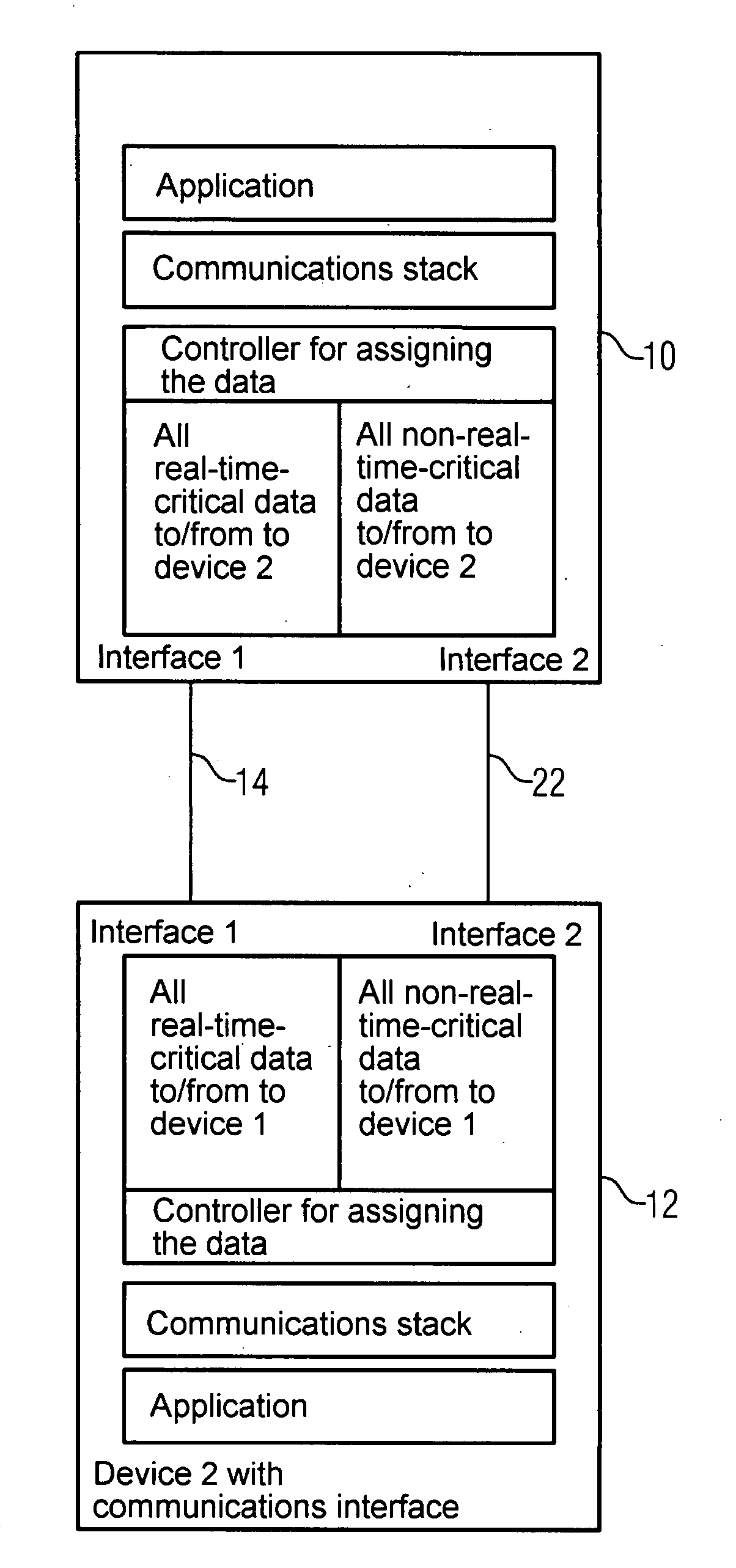
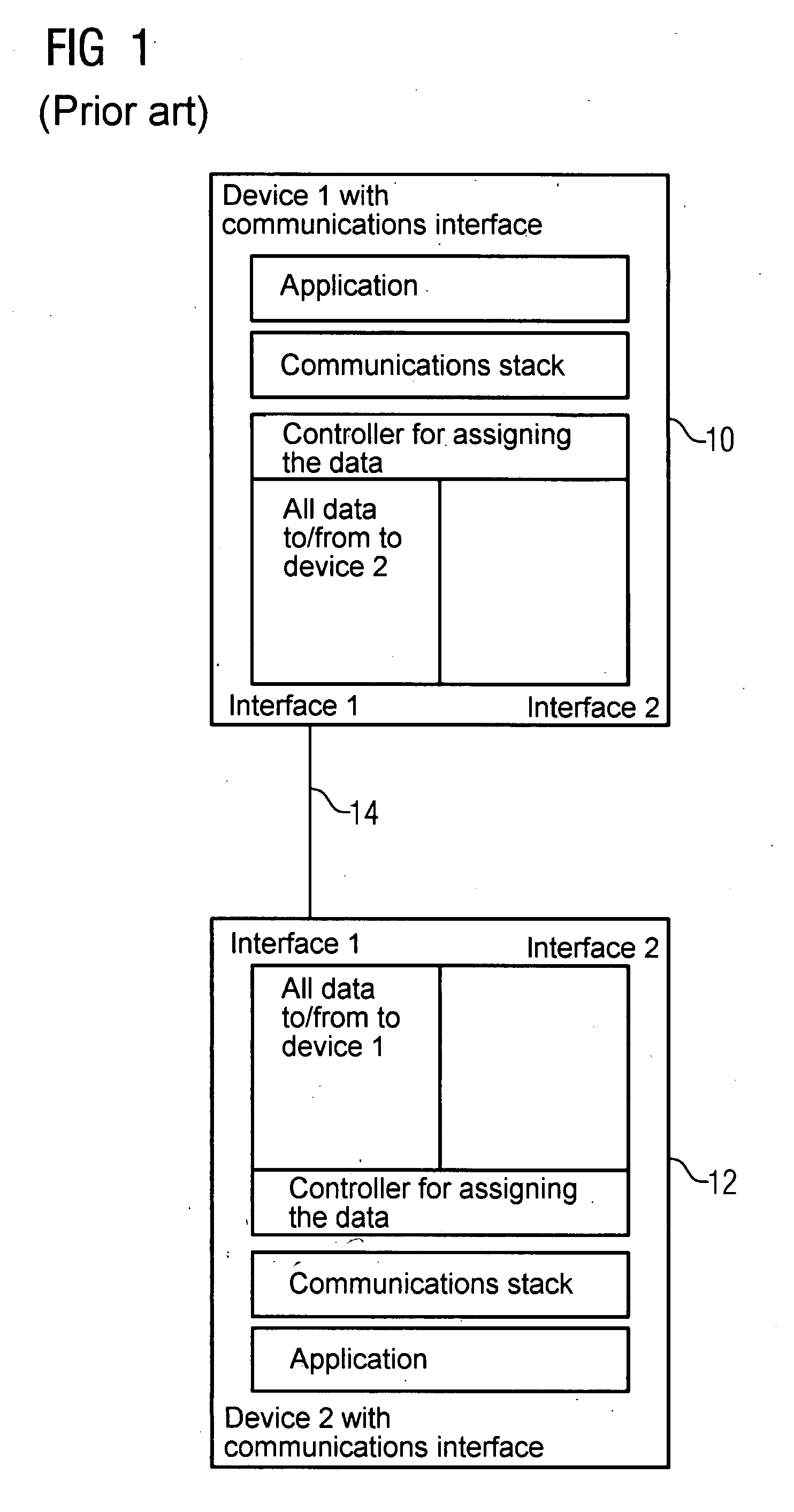
[0026]FIG. 1 shows a section of a communication system of the prior art with two subscribers, namely with a first device 10 and with a second device 12. Both devices can both send and receive. The subscribers 10 and 12 are connected to each other via a data line 14. The data line is connected for both devices 10 and 12 to the respective interface 1 of the subscribers. The respective interfaces 2 of the first device 10 and of the second device 12 are shown here as not connected. However a further subscriber of the communication system could be connected in each case via the two interfaces 2.

[0027]The software control of the respective devices is undertaken in the units “application”, “communications stack” and a controller for assignment of the data. The control allocates all data which is sent to the second device 12 or is received by this device to interface 1. Accordingly the second device 2 also includes a controller for assignment of the data which assigns all data which origina...


PUM


Abstract

A transmission of data in a communication system, e.g., a switched network with a plurality of subscribers who are interconnected in pairs via data circuits, especially lines is provided. At least one of the pairs of subscribers is interconnected via first line or a separate second line. The first line is used for transmitting real-time-critical data between the pair of subscribers while the second line is used for transmitting non-real-time-critical data between the pair of subscribers.

Description

CROSS REFERENCE TO RELATED APPLICATIONS[0001]This application is the U.S. National Stage of International Application No. PCT / EP2006 / 061733, filed Apr. 21, 2006 and claims the benefit thereof. The International Application claims the benefits of German application No. 102005019105.3 DE filed Apr. 25, 2005, both of the applications are incorporated by reference herein in their entirety.FIELD OF INVENTION[0002]The invention relates to a communication system, for example a switched network, with a plurality of subscribers that are connected to each other (in pairs) over data connections, especially lines.BACKGROUND OF INVENTION[0003]A switched network is described for example in DE 100 58 524 A1. Subscribers of a switched network can be computers, programmable logic controllers or other devices which exchange data with other machines, especially process such data. By contrast with bus systems in which any subscriber can reach any other subscriber directly via the data bus, a switched n...

Claims


Application Information

Patent Timeline
IPC IPC(8): H04L12/56
CPCH04L12/6418H04M7/1275H04L2012/6459H04L65/1053
Inventor FRANKE, MICHAEL
Owner SIEMENS AG
Why Eureka
Try Eureka