
Audio Signal Loudness Measurement and Modification in the MDCT Domain

a technology of audio signal and loudness measurement, applied in the field of audio signal processing, can solve the problems of difficult use of this transform, inability to accurately represent the steady state nature, and complex psychoacoustic methods, and achieve the effects of small average error, small average error, and reduced integration tim

Inactive Publication Date: 2009-12-10
DOLBY LAB LICENSING CORP
View PDF99 Cites 37 Cited by
  • Summary
  • Abstract
  • Description
  • Claims
  • Application Information

AI Technical Summary

Benefits of technology

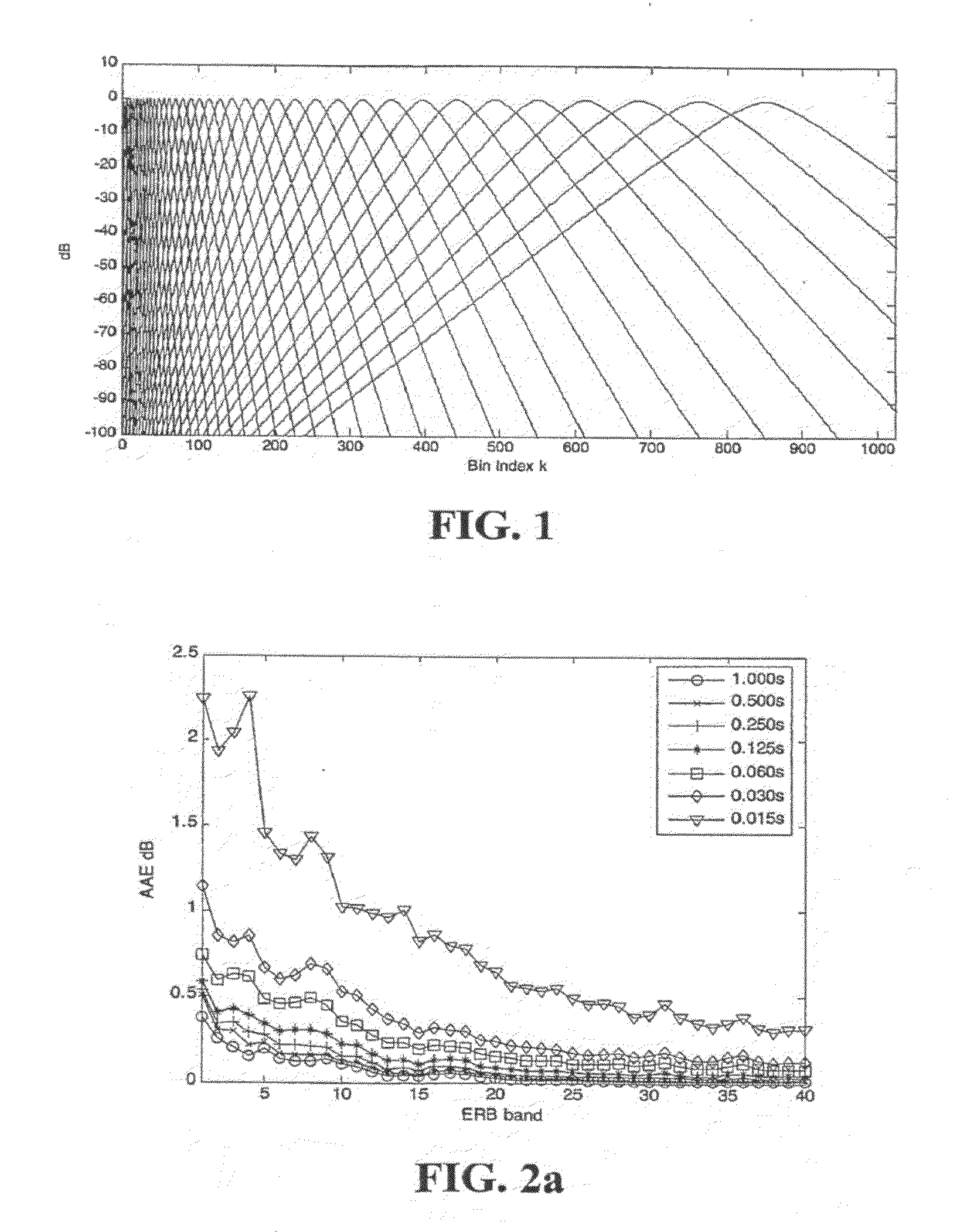
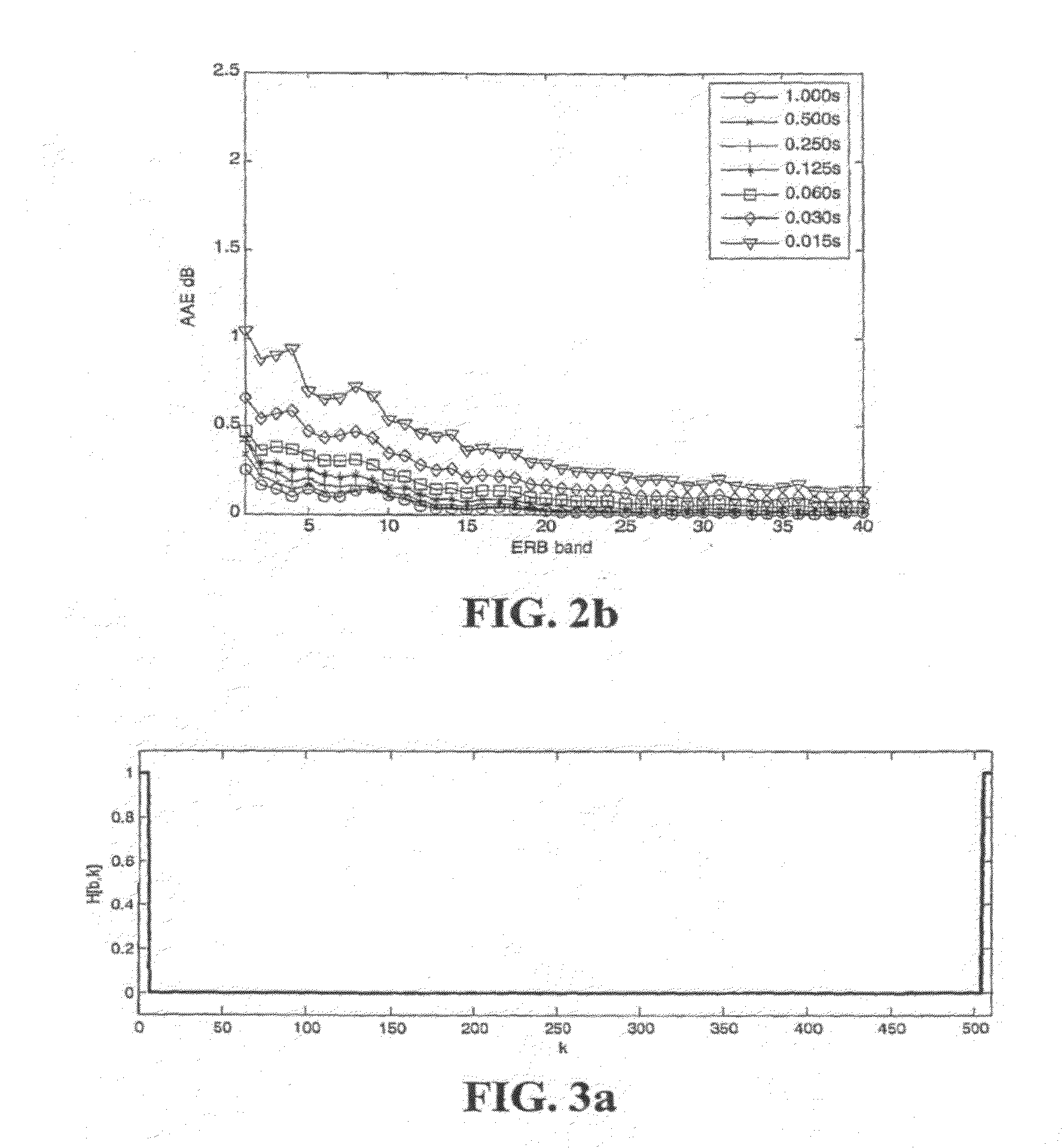
The patent text describes a method for estimating the power spectrum of a signal by averaging the squared magnitude of the signal over many blocks. This method is useful for computing various objective loudness measures of a signal. The text also discusses alternative methods for approximating the power spectrum using a moving average or a single-pole smoothing filter. The text also mentions that the power spectrum can be estimated from the MDCT using critical band filters and that the accuracy of the power spectrum estimation depends on the size of the averaging window. The technical effect of the patent text is to provide a reliable and accurate method for estimating the power spectrum of a signal, which is useful for computing various objective loudness measures.

Problems solved by technology

Psychoacoustic methods are typically more complex and aim to better model the workings of the human ear.
Properties of the MDCT (and similarly the DCT) lead to difficulties when using this transform when performing spectral analysis and modification.
When successive and overlapping MDCT's are used to analyze a substantially steady state signal, successive MDCT values fluctuate and thus do not accurately represent the steady state nature of the signal.
In the case of frequency domain processing, additional forward and inverse FFTs impose a significant increase in computational complexity and it would be beneficial to dispense with these computations and process the MDCT spectrum directly.
In general, such filtering introduces artifacts to the processed audio, but it will be shown that if the filter varies smoothly across frequency, then the artifacts become perceptually negligible.

Method used


Image

  • Audio Signal Loudness Measurement and Modification in the MDCT Domain
  • Audio Signal Loudness Measurement and Modification in the MDCT Domain
  • Audio Signal Loudness Measurement and Modification in the MDCT Domain

Examples


Embodiment Construction

[0085]Aspects of the present invention provide for measurement of the perceived loudness of an audio signal that has been transformed into the MDCT domain. Further aspects of the present invention provide for adjustment of the perceived loudness of an audio signal that exists in the MDCT domain.

Loudness Measurement in the MDCT Domain

[0086]As was shown above, properties of the STMDCT make loudness measurement possible and directly using the STMDCT representation of an audio signal. First, the power spectrum estimated from the STMDCT is equal to approximately half of the power spectrum estimated from the STSDFT. Second, filtering of the STMDCT audio signal can be performed provided the impulse response of the filter is compact in time.

[0087]Therefore techniques used to measure the loudness of an audio using the STSDFT and STDFT may also be used with the STMDCT based audio signals. Furthermore, because many STDFT methods are frequency-domain equivalents of time-domain methods, it follo...


PUM


Abstract

Processing an audio signal represented by the Modified Discrete Cosine Transform (MDCT) of a time-sampled real signal is disclosed in which the loudness of the transformed audio signal is measured, and at least in part in response to the measuring, the loudness of the transformed audio signal is modified. When gain modifying more than one frequency band, the variation or variations in gain from frequency band to frequency band, is smooth. The loudness measurement employs a smoothing time constant commensurate with the integration time of human loudness perception or slower.

Description

TECHNICAL FIELD[0001]The invention relates to audio signal processing. In particular, the invention relates to the measurement of the loudness of audio signals and to the modification of the loudness of audio signals in the MDCT domain. The invention includes not only methods but also corresponding computer programs and apparatus.REFERENCES AND INCORPORATION BY REFERENCE[0002]“Dolby Digital” (“Dolby” and “Dolby Digital” are trademarks of Dolby Laboratories Licensing Corporation) referred to herein, also known as “AC-3” is described in various publications including “Digital Audio Compression Standard (AC-3),” Doc. A / 52A, Advanced Television Systems Committee, 20 Aug. 2001, available on the Internet at www.atsc.org.[0003]Certain techniques for measuring and adjusting perceived (psychoacoustic loudness) useful in better understanding aspects the present invention are described in published International patent application WO 2004 / 111994 A2, of Alan Jeffrey Seefeldt et al, published De...

Claims


Application Information

Patent Timeline
Patent Type & Authority Applications(United States)
IPC IPC(8): H04R29/00
CPCG10L25/69G10L19/0212
Inventor SEEFELDT, ALAN JEFFREYCROCKETT, BRETT GRAHAMSMITHERS, MICHAEL JOHN
Owner DOLBY LAB LICENSING CORP
Learn More