Methods and Systems for Provisioning Energy Systems

a technology of energy systems and energy systems, applied in lighting and heating equipment, instruments, scene recognition, etc., can solve the problems of increasing environmental and cost concerns associated with traditional energy systems, homeowners remaining reluctant to convert from conventional fuel based systems to advanced solar and other alternative energy technologies, and the current marketplace does not offer consumers sufficient information about the cost and benefits of energy systems

Active Publication Date: 2009-12-10
SUNGEVITY
View PDF32 Cites 170 Cited by
  • Summary
  • Abstract
  • Description
  • Claims
  • Application Information

AI Technical Summary

Problems solved by technology

Environmental and cost concerns associated with traditional energy systems are increasing in today's energy conscious society.
Yet, despite these advantages and incentives many homeowners remain reluctant to convert from conventional fuel based systems to advanced solar and other alternative energy technologies.
Part of the reluctance stems from the time, expertise and cost associated with converting from a conventional energy system to an alternative energy system such as a solar energy system.
The current marketplace does not offer consumers sufficient information about costs and

Method used


Image

  • Methods and Systems for Provisioning Energy Systems
  • Methods and Systems for Provisioning Energy Systems
  • Methods and Systems for Provisioning Energy Systems

Examples


first embodiment

[0082]The term ‘sizing’ as used herein refers to obtaining or generating length and width measurements for a generally rectangular planar installation surface such as a side of a roof. An installation surface is a surface area of a roof, for example a roof side contemplated for installation of energy system components. According to some embodiments of the invention, sizing of an installation surface is carried out by a sizing subsystem 500 automatically or at least partly automatically by means of user interaction with a GUI 560 of system 500.

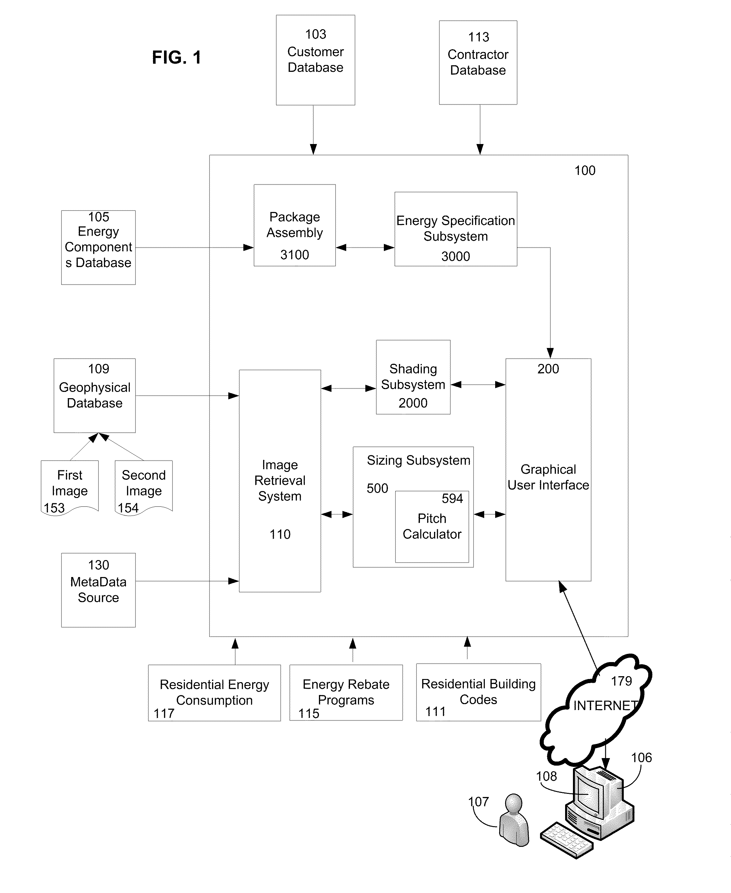
[0083]FIG. 5 illustrates a remote sizing subsystem 500 according to an embodiment of the invention. Subsystem 500 includes a graphical user interface 560 configured for communication with a computer system 506 accessible by a user 507. GUI 560 is further configured for communication with an image retrieval subsystem such as subsystem 110 illustrated in FIG. 1. GUI 560 provides images for display on display device 508 of user system 506. By inte...

second embodiment

[0105]Alternative embodiments of sizing subsystem 500 are illustrated in FIGS. 11-19. FIG. 11 illustrates various example embodiments of an interactive measuring tool (1150, 1107, and 1117) for use in sizing surfaces such as roof of house 600 in FIG. 6. In one embodiment of the invention at least one of tools 1150, 1107 and 1117 are displayed in a viewport 110 to a user. A user selects a tool to use for measuring. User manipulation of a selected measuring tool positions the tool with respect to first and second images depicting the same surface, for example roof of house 600 in FIG. 6. The measuring tool is rotatable and scalable by user 507 to align at least two sides of the tool an image of an object to be measured, for example a roof surface to be measured.

[0106]In one example embodiment of the invention, a user selects tool 1150 from viewport 1100. In one embodiment dimensions of side 1187 and 1177 of interactive measuring tool 1150 are calibrated before displaying tool 1150 in ...


PUM


Abstract

The invention provides consumers, private enterprises, government agencies, contractors and third party vendors with tools and resources for gathering site specific information related to purchase and installation of energy systems. A system according to one embodiment of the invention remotely determines the measurements of a roof. An exemplary system comprises a computer including an input means, a display means and a working memory. An aerial image file database contains a plurality of aerial images of roofs of buildings in a selected region. A roof estimating software program receives location information of a building in the selected region and then presents the aerial image files showing roof sections of building located at the location information. Some embodiments of the system include a sizing tool for determining the size, geometry, and pitch of the roof sections of a building being displayed.

Description

CROSS REFERENCE TO RELATED APPLICATIONS[0001]This application claims the benefit of filing date of U.S. provisional application Ser. No. 61 / 025,431 titled “System and Method for Sizing a Roof for Installation of Solar Panels”, naming the same inventors and filed on Feb. 1, 2008 in the USPTO, the specification of which is incorporated herein, in its entirety, by reference. This application claims the benefit of PCT / US08 / 79003 filed Oct. 6, 2008 in the PCT receiving office of the USPTO, naming the same inventors, the specification of which is hereby incorporated herein, in its entirety, by reference. This application claims benefit of filing date of U.S. provisional application Ser. No. 61 / 047,086 titled Customer Relationship Management Module, Marketing Module, Quick Sizing filed on Apr. 22, 2008 in the USPTO, naming the same inventors, the specification of which is incorporated herein, in its entirety, by reference.FIELD OF THE INVENTION[0002]The present invention relates generally ...

Claims


Application Information

Patent Timeline
IPC IPC(8): G06K9/00G06F15/00G06V20/13
CPCG06K9/0063G06Q30/0603G06Q10/06F24S2201/00G06V20/13
Inventor KENNEDY, DANIEL IANPRYOR, ADAMBIRCH, ANDREW
Owner SUNGEVITY
Why Eureka
Try Eureka