Method and system for vacuum conveying of bulk material and computer program product

a vacuum conveying system and bulk material technology, applied in the field of methods and systems for vacuum conveying bulk material, can solve the problems of excessive wear, excessive load on the vacuum blower generating the conveying air flow, and obstruction so as to eliminate the adherence of powdery or bulk material and eliminate the clogging of the vacuum conveying system

Inactive Publication Date: 2009-12-10
SUN CHEM CORP
View PDF12 Cites 20 Cited by
  • Summary
  • Abstract
  • Description
  • Claims
  • Application Information

AI Technical Summary

Benefits of technology

[0007]It is an object of the present invention to provide an efficient vacuum conveying method and system for preventing adherence of bulk material or powdery material or clogging of a vacuum conveying system of the aforementioned type.
[0008]According to still another aspect of the present invention there is to be provided a computer program product for use in the aforementioned vacuum conveying system for controlling the controlling device of the vacuum conveying system such as to efficiently prevent adherence of bulk material or powdery material and clogging of the system.
[0011]By applying high pressure gas the flexible circumferential wall or flexible section of the tube is inflated and thus locally stretched, which causes adhering particles to flake or peel off from the flexible circumferential wall or section. Thus, according to the present invention adherence of powdery or bulk material and even clogging of the vacuum conveying system is eliminated.
[0012]Thus, in principle according to the present invention the vacuum conveying system may consist of both rigid tubes and flexible hoses depending on the design of the overall vacuum conveying system. In principle, the tubes may comprise subsections having flexible walls. However, preferably all conveying tubes of the vacuum conveying system are formed as hoses having flexible circumferential walls. At certain subsections of the system, in particular at bulk material discharging sections for feeding the powdery or bulk material and at bulk material receiving sections, such as filters or storage vessels, the circumferential walls may also comprise rigid walls. At such sections it is, however, preferred to provide a double-layer structure of these walls, including a tubular outer wall, which is rigid, and a lining of a flexible material covering the inner surface of the tubular wall. Preferably, the lining is linked with the inner surface only at discrete locations spaced apart from each other so that a free space can remain between the inner surface and the lining, which can be used for applying high-pressure air or vacuum to either inflate or stretch the flexible lining or to suck the flexible lining onto the inner surface of the respective section of the vacuum conveying system. Thus, adherence of powdery or bulk material on the inner surface of the flexible lining is effectively eliminated.
[0013]According to another embodiment of the present invention valves disposed at respective ends of said vacuum conveying system and / or dividing said vacuum conveying system into subsections are closed, when said pressurized gas is applied to said vacuum conveying system or to a respective subsection thereof so that those sections of the system comprising flexible walls can be inflated to eliminate adherence of powdery or bulk material.

Problems solved by technology

A general problem with vacuum conveying of bulk material, i.e. of material consisting of free flowing particles or powdery material, such as powder, ground stone powder or toner particles, in processing plants is adherence of bulk material to the inner circumferential walls of tubes or hoses used for conveying the bulk material, which causes clogging of the tubes or hoses and imparts an excessive load onto the vacuum blower generating the conveying air flow.
However, imposing mechanical vibrations to the tubes may result in an excessive wearing down and even destruction of the tubes, which might give rise to the formation of small cracks and holes in the walls of the tubes.
Such cracks and holes could cause an unwanted leakage and result in an uncontrolled leaking of powdery materials towards the outside, which is undesirable.
On the other hand, the above mentioned approach of imposing mechanical vibrations to conveying hoses or tubes of a vacuum conveying system is not suitable, because the walls of the conveying hoses or tubes will be more prone to wear and tear and mechanical destructions.

Method used


Image

  • Method and system for vacuum conveying of bulk material and computer program product
  • Method and system for vacuum conveying of bulk material and computer program product
  • Method and system for vacuum conveying of bulk material and computer program product

Examples


Embodiment Construction

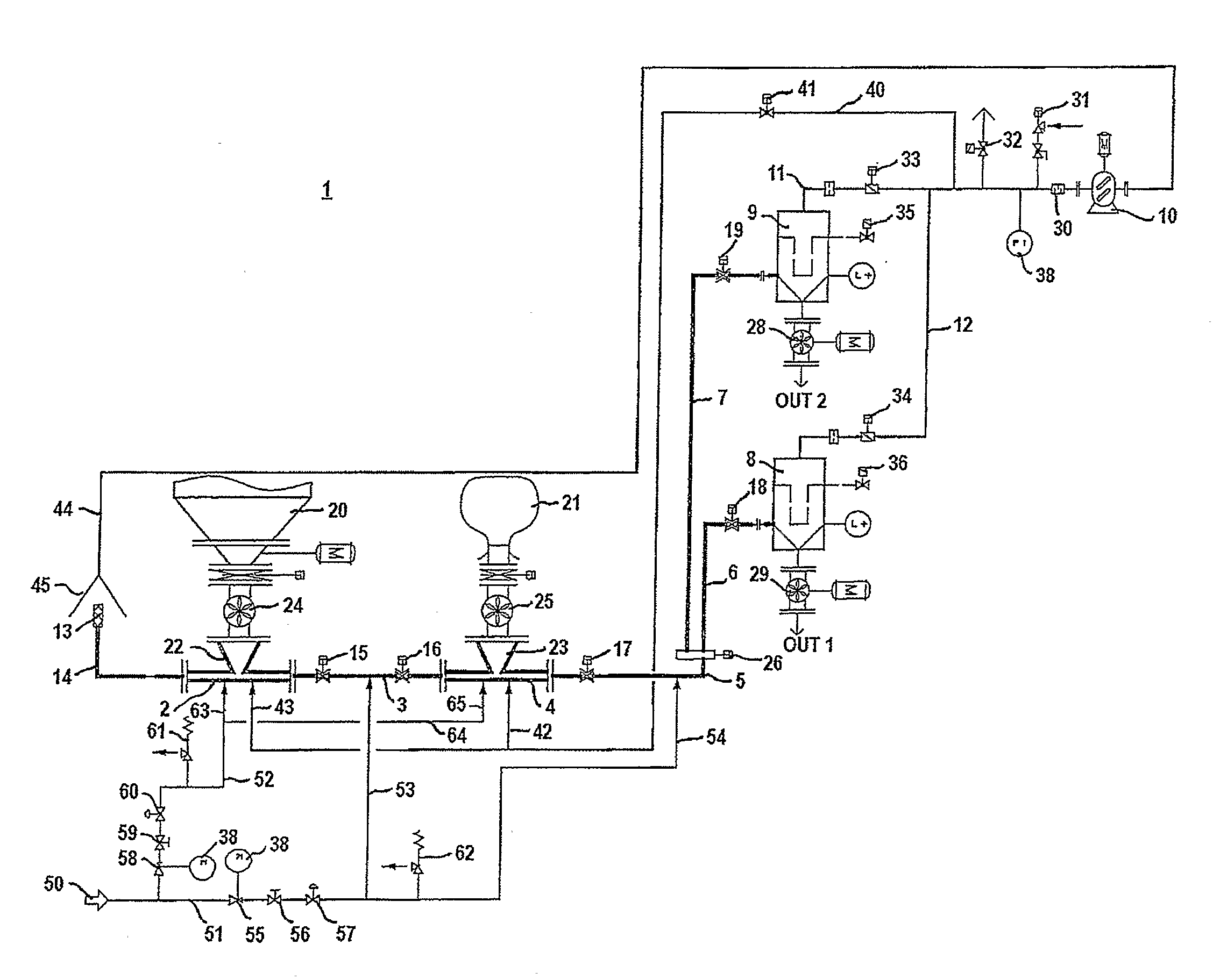
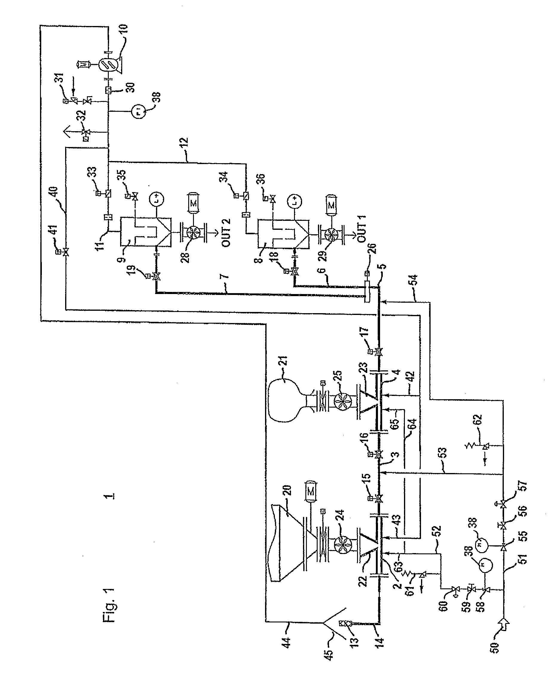
[0023]In the following, the overall configuration of the vacuum conveying system 1 will be described with reference to FIG. 1 first. Referring to FIG. 1, the vacuum conveying system 1 consists of a plurality of conveying hoses 5 to 7 for connecting the bulk material receiving sections 8, 9 with bulk material discharging sections 2, 4. More specifically, the first bulk material discharging section consists of a tube 2 having a hopper 22, which is unitarily provided with the tube 2. The first bulk material discharging section 2 is connected, via rotary valve 24, with a silo container 20 used for storing bulk material, such as a powder. The first discharging section 2 is connected, via connecting hose 3, with a second bulk material discharging section 4 of similar configuration. More specifically, the second bulk material discharging section 4 consists of a tube 4 having a hopper 23, which is unitarily connected with the tube 4. The second bulk material discharging section 4 is connect...


PUM


Abstract

The invention relates to a method for vacuum conveying bulk material in a vacuum conveying system (1) which comprises: a plurality of tubes (2-6) for conveying bulk material, at least some of said tubes having flexible walls (71), a vacuum blower (10) disposed at a first end of said vacuum conveying system (1) for generating a conveying gas flow within said vacuum conveying system (1), a bulk material discharging section (22, 23) for discharging bulk material into said vacuum conveying system (1), and a bulk material receiving section (8, 9) communicating with said vacuum blower (10), for receiving bulk material conveyed by said gas flow from said bulk material discharging section (22, 23). According to the invention, the method comprises the steps of: disconnecting said vacuum blower (10) from said vacuum conveying system (1); and applying pressurized gas to said vacuum conveying system (1) or at least to a subsection thereof for stretching or inflating said flexible walls (71) to thereby reduce adherence of bulk material to said flexible walls (71). Other aspects of the invention relate to a corresponding vacuum conveying system, to a controlling device and a computer program product for controlling the vacuum conveying system in accordance with the above method steps.

Description

FIELD OF INVENTION[0001]The present invention relates to a method and system for vacuum conveying of bulk material and relates more specifically to a method, a system, a controlling device and a computer program product for preventing clogging of components of a vacuum conveying system used for vacuum conveying bulk material.BACKGROUND OF INVENTION[0002]Vacuum conveying systems for vacuum conveying of bulk material are well-known. In vacuum conveying systems a vacuum blower usually generates vacuum or negative pressure in a system of tubes and / or hoses used for conveying the bulk material for conveying bulk material from a bulk material discharging section, which is used for discharging bulk material into the system, to a downstream bulk material receiving section, e.g. a storage container or processing stage. The vacuum blower generates an air flow in the tubes and / or hoses which conveys the bulk material.[0003]A general problem with vacuum conveying of bulk material, i.e. of mater...

Claims


Application Information

Patent Timeline
Patent Type & Authority Applications(United States)
IPC IPC(8): B65G53/66B65G53/04G06F7/00
CPCB65G53/54B65G53/521
Inventor STROHSCHEIN, DIETMAR
Owner SUN CHEM CORP
Why Eureka
Try Eureka