Rotary separator drum seal

a drum seal and separator technology, applied in the direction of machines/engines, stators, liquid fuel engines, etc., can solve the problems of unsuitable separated fluids (e.g. liquids)

Inactive Publication Date: 2009-12-10
DRESSER RAND CO
View PDF103 Cites 44 Cited by
  • Summary
  • Abstract
  • Description
  • Claims
  • Application Information

AI Technical Summary

Benefits of technology

[0003]To prevent inflow of inlet fluids to the outlet flow, and thus preventing remixing of separated fluids (e.g., liquids), the drum outlet end is normally sealed against a static member located adjacent to the drum. Such a static member may be a partition wall (e.g., diaphragm) in a fluid machine, an inlet wall of a compressor, a casing wall of a stand alone separator, etc. As there must be some clearance between the drum end and the static member to allow free rotation of the drum, the seal between the drum and static member is typically non-contact. However, with previously known seal designs, there is a risk of undesired separated fluids (e.g., liquids) from passing through the clearance space and back into the outlet fluid stream.SUMMARY OF THE INVENTION
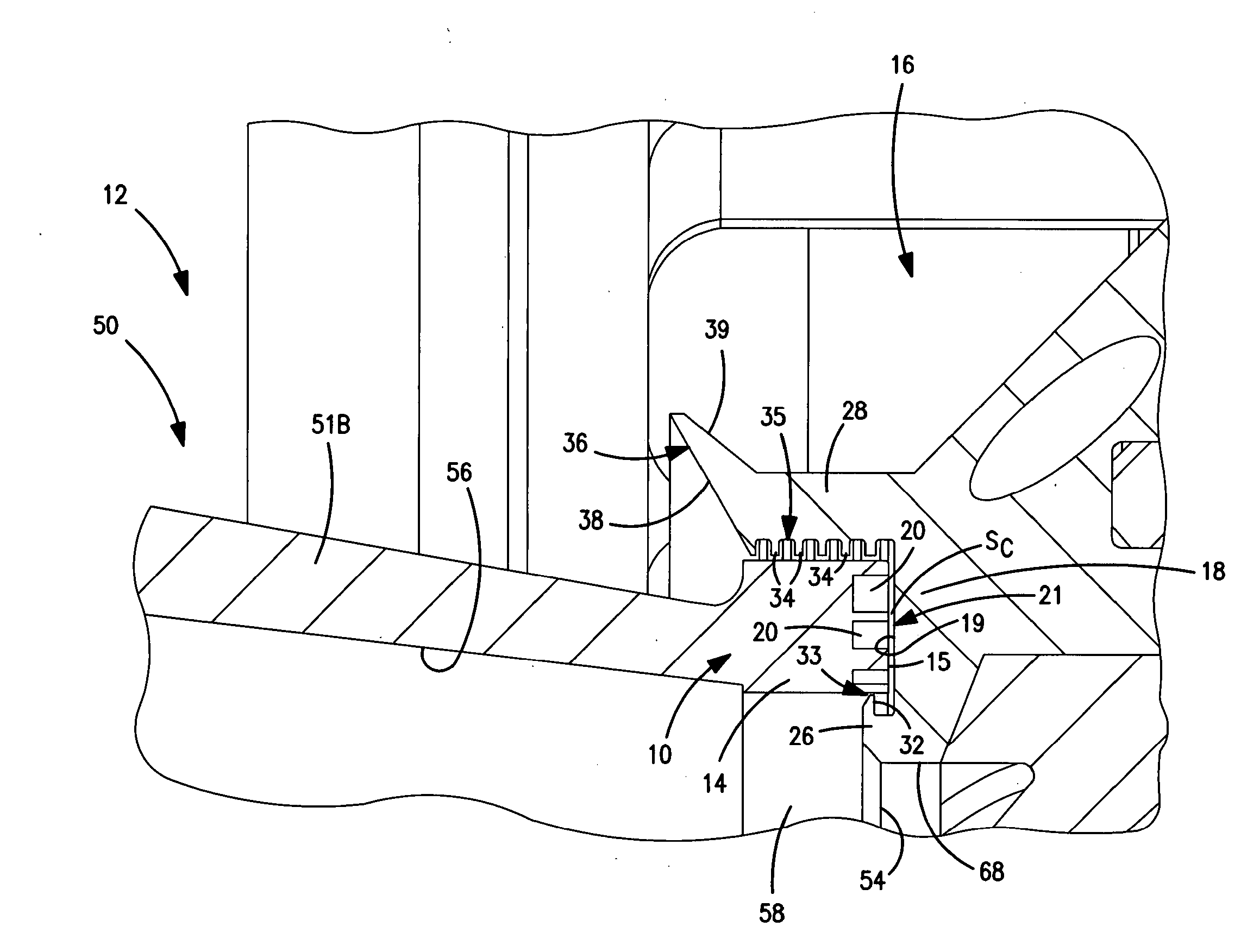
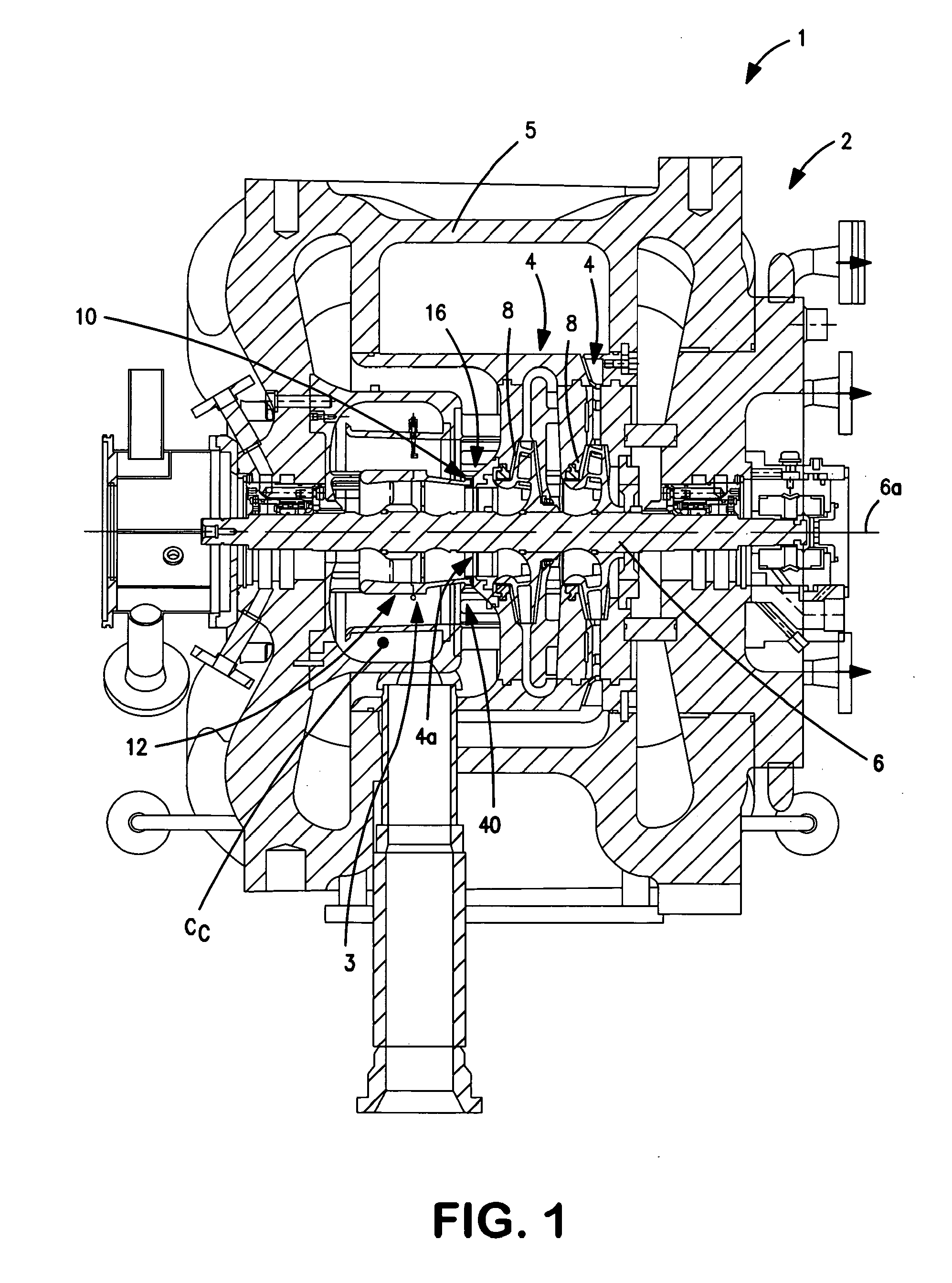
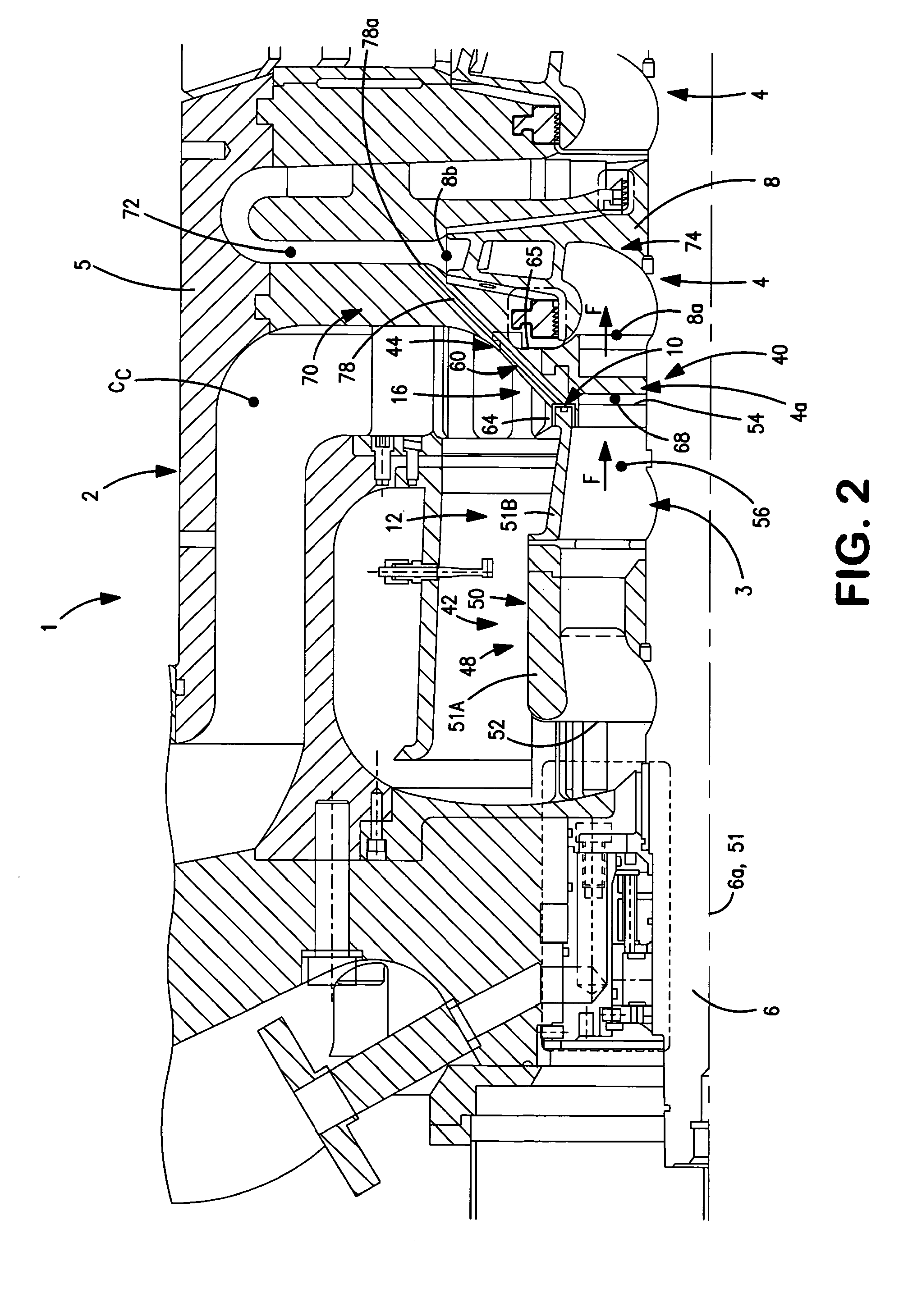
[0004]In one aspect, the present invention is a seal assembly for a fluid machine including a casing and a shaft disposed within the casing so as to be rotatable about a central axis. The seal assembly comprises a static member generally fixedly disposed within the casing and having an end surface and a rotatable member coupled with the shaft and spaced axially from the static member. The rotatable member has an axial end with a generally radial end surface extending circumferentially about the shaft axis, the rotatable member end surface being located adjacent to and facing the static member end surface such that a clearance space is defined generally between the two end surfaces. The rotatable member further has a plurality of openings extending generally axially inwardly from the rotatable member end surface and spaced circumferentially about the shaft axis such that land surface sections are defined on the end surface. The land surface sections or / and the openings are configured to at least generally prevent fluid flow radially inwardly through the clearance space.

Problems solved by technology

However, with previously known seal designs, there is a risk of undesired separated fluids (e.g., liquids) from passing through the clearance space and back into the outlet fluid stream.

Method used


Image

  • Rotary separator drum seal
  • Rotary separator drum seal
  • Rotary separator drum seal

Examples


Embodiment Construction

[0016]Certain terminology is used in the following description for convenience only and is not limiting. The words “right”, left”, “lower”, “upper”, “upward”, “down” and “downward” designate directions in the drawings to which reference is made. The words “inner”, “inwardly” and “outer”, “outwardly” refer to directions toward and away from, respectively, a designated centerline or a geometric center of an element being described, the particular meaning being readily apparent from the context of the description. Further, as used herein, the word “connected” is intended to include direct connections between two members without any other members interposed therebetween and indirect connections between members in which one or more other members are interposed therebetween. The terminology includes the words specifically mentioned above, derivatives thereof, and words of similar import.

[0017]Referring now to the drawings in detail, wherein like numbers are used to indicate like elements ...


PUM


Abstract

A seal assembly for a compressor includes a static member fixedly disposed within a compressor casing and having an end surface and a rotatable separator coupled with a compressor shaft and spaced from the static member. The separator has an axial end with a radial end surface located adjacent to the static member end surface such that a clearance space is defined therebetween. The separator has a plurality of openings extending inwardly from the end surface and spaced about the shaft axis such that land surface sections are defined on the end surface. The land surface sections or / and the openings are configured to prevent fluid flow radially inwardly through the clearance space. The static member has two annular walls receiving an end portion of the separator, with annular ridges providing labyrinth seals disposed against inner and outer surfaces of the separator, and an annular deflector with an angled deflector surface.

Description

[0001]The present invention relates to fluid machinery, and more particularly to seal assemblies for rotary fluid separators.[0002]Rotary separators for separating solids from fluids, liquids from gases, or / and gases or liquids of varying density are known. Such rotary separators typically include a rotatable tubular body or “drum” having a central bore with inlet and outlet ends. With this structure, fluid flow enters the inlet end and passes through the bore, such that heavier fluids (e.g., liquids) are directed outwardly onto a drum inner surface, and generally pass through openings therethrough for collection, while the lighter fluids (e.g., gas) pass through an outlet end of the drum. Typically, fluid flow out of the drum outlet is directed into one or more passages, such as an inlet of a compressor or an outlet pipe of a “stand alone” separator device.[0003]To prevent inflow of inlet fluids to the outlet flow, and thus preventing remixing of separated fluids (e.g., liquids), t...

Claims


Application Information

Patent Timeline
Patent Type & Authority Applications(United States)
IPC IPC(8): F04D29/70F16J15/447F04D29/10
CPCF04D29/083F04D29/102F16J15/444F16J15/44F04D29/701
Inventor MAIER, WILLIAM C.
Owner DRESSER RAND CO
Why Eureka
Try Eureka