Pressure sensing catheter

a pressure sensing catheter and catheter technology, applied in the field of catheters, can solve the problems of difficult to determine whether residual air bubbles are present in the filled catheter, patient must endure a longer procedure, and the removal of all bubbles may require several filling and vacuum application cycles, so as to increase the overall accuracy and ease of pressure sensing procedure, the effect of reducing the amount of time and reducing the number of procedures

Active Publication Date: 2009-12-10
GENTERA HLDG
View PDF8 Cites 53 Cited by
  • Summary
  • Abstract
  • Description
  • Claims
  • Application Information

AI Technical Summary

Benefits of technology

[0007]This invention overcomes the disadvantages of the prior art by providing a pressure sensing catheter, and method for using the same, that eliminates the practitioners' need to fill the catheter with fluid manually prior to insertion, and thereby increases the accuracy and ease of the overall pressure-sensing procedure. The illustrative catheter includes, in its proximal end, a transducer base or housing that is permanently attached to the catheter shaft. The base includes, inserted thereinto, one or more miniaturized pressure transducer assemblies, which are in fluid communication with corresponding pressure lumens th

Problems solved by technology

Thus, removal of all bubbles may require several fill and vacuum-application cycles.
This is a time-consuming process, and may lead to inaccuracies if air bubbles remain.
It may be difficult to determine whether residual air bubbles are present in the filled catheter, particularly when the catheter is already inserted into the patient.
In addition, the extra time required to fill the catheter with fluid means that th

Method used


Image

  • Pressure sensing catheter
  • Pressure sensing catheter
  • Pressure sensing catheter

Examples


Embodiment Construction

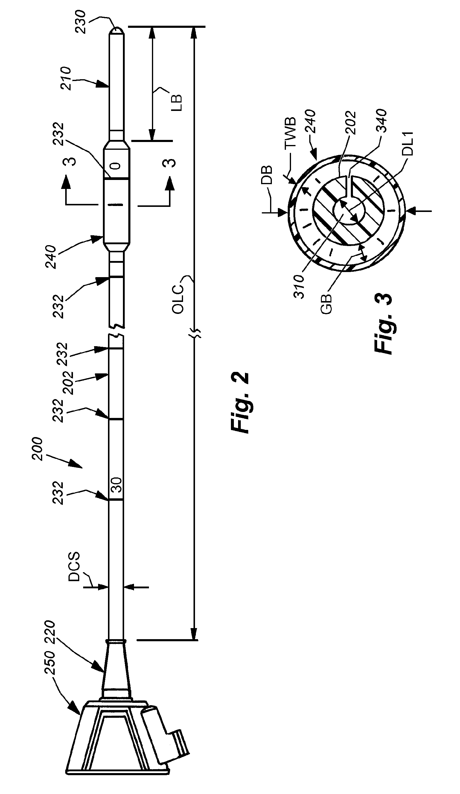
[0035]FIG. 2 shows a pressure sensing catheter 200 according to an illustrative embodiment of this invention. The catheter 200 includes a shaft 202 having a distal end 210 adapted for insertion into a body cavity of the patient and an opposing proximal end 220 that remains posterior of the patient to be accessed by the practitioner. The distal end includes a rounded over tip 230 that is sealed against moisture infiltration in this embodiment. The tip allows for easier guiding of the distal end 210 into a body cavity or other location. The catheter 200 of this example is a urodynamic catheter, and its shaft 202 has an overall length OLC of approximately 54 centimeters in one embodiment. The overall length of the shaft is highly variable to suit other applications, including rectal catheters, an example of which will also be described below. As shown, the shaft 202, which is constructed from a semi-rigid / flexible polymer to be described further below, includes a series of printed-on o...


PUM

PropertyMeasurementUnit
Pressureaaaaaaaaaa

Abstract

This invention provides a pressure sensing catheter, and method for using the same, which eliminates the practitioners' need to fill the catheter with fluid manually prior to insertion, and thereby increases the accuracy and ease of the overall pressure-sensing procedure. The illustrative catheter includes, in its proximal end, a transducer base or housing that is permanently attached to the catheter shaft. The base includes, inserted thereinto, one or more miniaturized pressure transducer assemblies, which are in fluid communication with corresponding pressure lumens that extend down the shaft and are in communication with one or more predetermined balloons by discrete channels or ports, which provide a fluid passage between the interior space of the balloon and the corresponding pressure lumen. The integral assembly includes a predetermined, previously installed charge of fluid that extends from the transducer, through the corresponding pressure lumen and into the interior volume of the sensing balloon. The charge of fluid has been made free of any air bubbles at the point of manufacture, and is delivered fully charged, so that maximum sensing accuracy and minimum setup time are achieved. In alternate embodiments the catheter can include a fluid infusion/flushing lumen and port interconnected to a proximal fluid connection.

Description

RELATED APPLICATIONS[0001]This application claims the benefit of U.S. Provisional Application Ser. No. 61 / 059,992, filed Jun. 9, 2008, entitled PRESSURE SENSING CATHETER, the entire disclosure of which is herein incorporated by reference.FIELD OF THE INVENTION[0002]This invention relates to catheters for sensing the pressure of internal body regions.BACKGROUND OF THE INVENTION[0003]Pressure sensing catheters are used in a variety of medical procedures. Such catheters can be employed to sense pressure in rectal or urodynamic applications, being positioned within the urethra or bladder or another internal location within the body. Pressure-sensing catheters may also be applied to the rectum, vagina, or another internal location within the body in which pressure readings are desired. With reference to FIG. 1, a pressure sensing catheter 100 according to a typical prior art implementation is shown. In this example, the catheter 100 has been inserted transurethrally into the subject pati...

Claims


Application Information

Patent Timeline
IPC IPC(8): A61B5/03A61M25/16A61F2/958
CPCA61B5/205A61M25/1011Y10T29/49826A61M2025/0002A61M2205/3331A61M25/1036
Inventor WOODRUFF, DAVID M.LEOPOLD, PHILLIP M.
Owner GENTERA HLDG
Why Eureka
Try Eureka