Intramedullary nail with oblique openings

a technology of intramedullary nail and oblique opening, which is applied in the field of orthopaedics, can solve the problems of complex devastating fractures, femur and tibia frequently fractures, and trauma to long bones, and achieve the effect of improving stability

Active Publication Date: 2009-12-10
BIOMET CV
View PDF41 Cites 72 Cited by
  • Summary
  • Abstract
  • Description
  • Claims
  • Application Information

AI Technical Summary

Benefits of technology

[0025]An embodiment of the present invention is in the form of an intramedullary nail containing a series of holes that allows for locking screws to be placed in various positions. The nail can be locked using a combination of screws, which allows various locking constructions. The nail of the present invention allows two separate screws to be placed through the nail, each screw in one of two different planes. The ability to use multiple screws in different planes allows better stability to be achieved with the locking screws.
[0026]The intramedullary nail of the present invention may be in the form of a Trochanteric Entry Nail (“TEN Nail”) design allowing for multiple screw fixation to be achieved in opposing planes for better fracture stabilization. As an alternative to this design, the Trochanteric Entry Nail may be adapted for use with two screws that are located in the same plane and extend into the femoral neck. In unstable femoral fractures, stability is necessary to facilitate the proper healing and the TEN Nail design of the present invention accomplishes the improved stability. In addition to using multiple planes, the screw creates a triangular geometry that aids in better axial and rotational stability.
[0027]According to the present invention, an intramedullary nail is provided with two transverse holes for reconstruction screws and an angulated crossing hole for a trochanteric screw that goes from the greater trochanter to the lesser trochanter regions of the femur for locking screw placement. The locking screws are placed through the nail in a combination in ways that, if one reconstruction screw and the trochanteric screw are utilized, an (X) shape appears in the medial to lateral plane. When this two-screw construction is observed down the axis of the nail, the screws have an (X) appearance. The opposing nature of the screw in this nail configuration gives the added stability that is desired for this type of fracture repair. The screw configuration can be changed, so that a combination of one or two screws can be used depending on the fixation that is desired based on a particular fracture pattern.
[0041]The technical advantages of the present invention also include the ability to allow for multiple screw fixations to be achieved in opposing planes for better fracture stabilization. For example, according to yet another aspect of the present invention, an intramedullary nail for use in the canal of a long bone is provided. The nail includes a body defining a longitudinal axis and an exterior periphery. The body has a first internal wall defining a first opening and a first opening centerline. The body also has a second internal wall defining a second opening having a second opening centerline. The first opening centerline and the second opening centerline are oblique with respect to each other. Each of the first opening and the second opening are adapted for receiving a screw. Thus the present invention provides for multiple screw fixation to be achieved in opposing planes for better fracture stabilization.
[0044]The technical advantages of the present invention also include the ability to use two screws that may provide for an x-shaped geometry that aids in better axial and rotational stability. For example, according to yet another aspect of the present invention, an intramedullary nail assembly is provided, including a nail having a first opening as well as a spaced-apart second opening. The first opening and the second opening are oblique with respect to each other. The first opening and the second opening define generally an x-shape. Each of the two openings may receive a screw. Thus the present invention provides for the use of two screws to provide an x-shaped geometry that aids in better axial and rotational stability.

Problems solved by technology

These long bones particularly are exposed to trauma from accidents, and as such often are fractured during such trauma and may be subject to complex devastating fractures.
Automobile accidents, for instance, are a common cause of trauma to long bones.
In particular, the femur and tibia frequently fracture when the area around the knee is subjected to a frontal automobile accident.
The lag screws have several different problems in use that are generally related to the lag screw not remaining in the proper position with respect to the intramedullary nail during the operating life of an implant.
Such a movement may render the patient non-ambulatory.
Another issue that may occur with lag screws is medial migration of a lag screw through the femoral head and into the pelvic cavity.
A further issue with an intramedullary nail lag screw is lateral migration or lateral pullout of the screw from the long bone.
Yet another problem with lag screws in trochanteric nail applications is the problem of neck collapse.
If the lag screw does not capture enough cancellous bone in the femoral neck, the neck and head may move laterally causing the phenomenon known as neck collapse and creating a leg length and other issues for the patient.
Medial migration is only one of many problems that occur with a fastener for use with orthopaedic prosthetic components.
The solid cross-section does not permit the nail to be introduced over a guide rod.
Thus, the nail is prevented from being used for comminuted and distal fractures of the femur because the closed surgical technique cannot be practiced.
In addition, adequate compression cannot be achieved due to the requirement to lock cross-nail.
The Russell-Taylor nail similarly requires a fully threaded locking screw and therefore does not permit sliding of the screw relative to the intramedullary rod.
Such multiple fractures are instable and the proper healing of such fractures is difficult.
Axial and rotational stability of such fractures may also be an issue.

Method used


Image

  • Intramedullary nail with oblique openings
  • Intramedullary nail with oblique openings
  • Intramedullary nail with oblique openings

Examples


Embodiment Construction

[0102]Embodiments of the present invention and the advantages thereof are best understood by referring to the following descriptions and drawings, wherein like numerals are used for like and corresponding parts of the drawings.

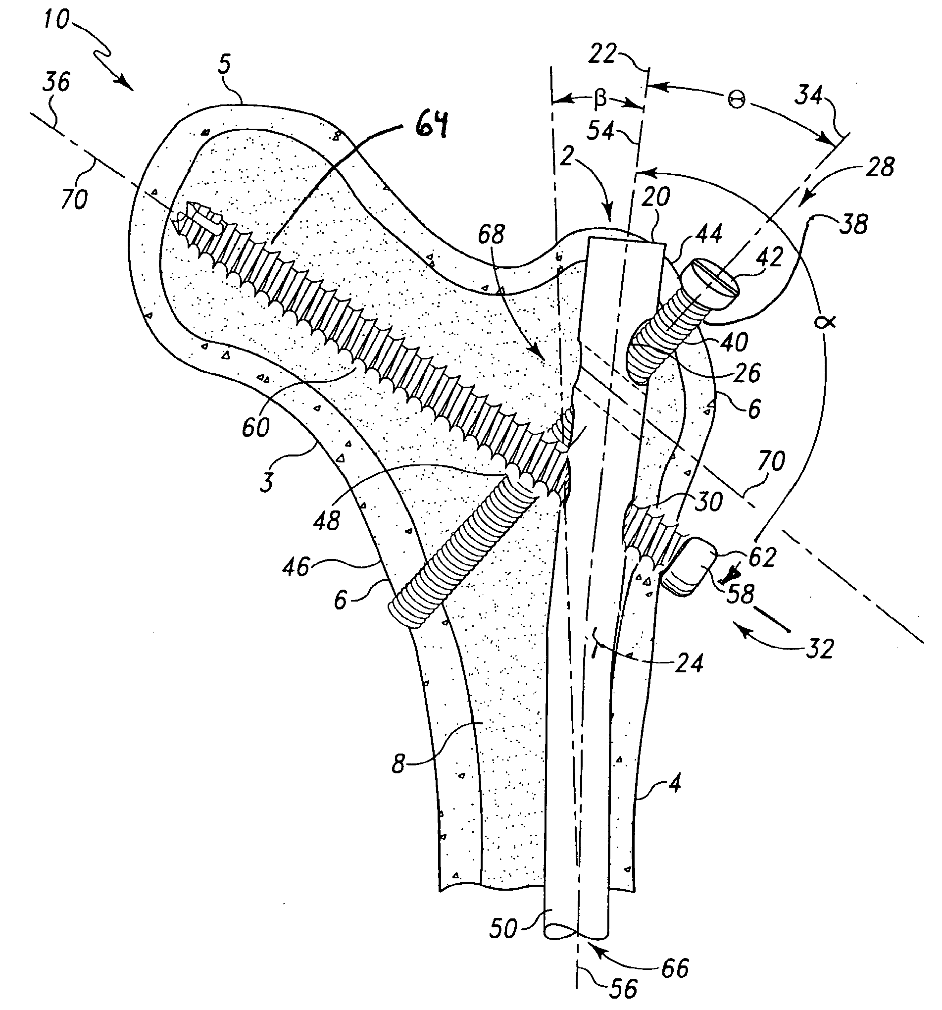
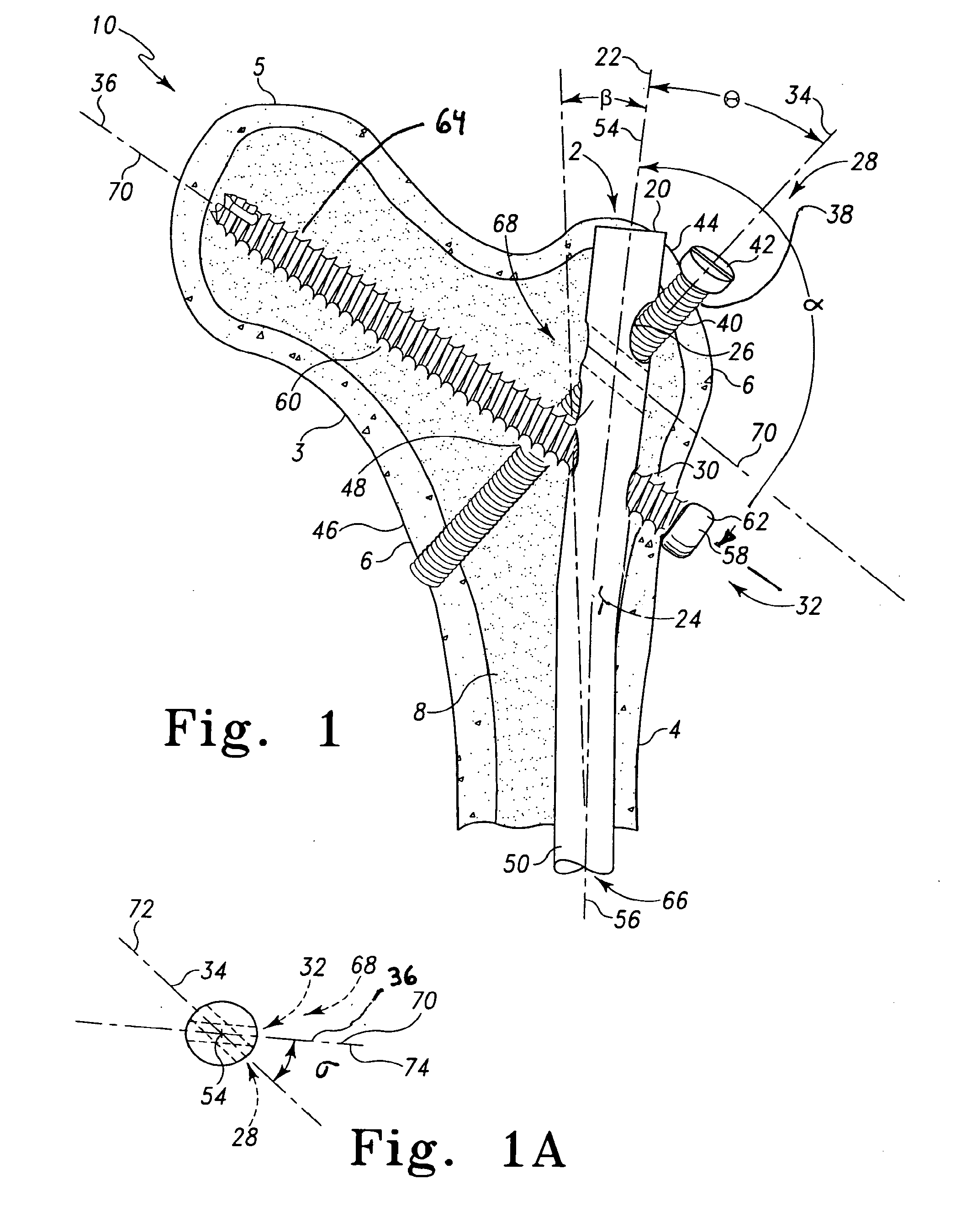
[0103]According to the present invention and referring now to FIG. 1, a first embodiment of the present invention is shown as intramedullary nail assembly 10. Intramedullary nail assembly 10 is used in a medullary canal 2 of a long bone 4. The nail assembly 10 includes a nail 20. The nail 20 defines a longitudinal axis 22 of the nail 20. The nail 20 further includes an external periphery 24 of the nail 20. The external periphery 24 of the nail 20 is adapted for fitting in the medullary canal 2 of the long bone 4. The long bone 4 may be any long bone in the human anatomy. For example, the long bone 4 may be a femur, a tibia, a humerus, or any other long bone. Preferably, the long bone in which the nail of the present invention is used is a humerus, a femur, or ...


PUM


Abstract

An intramedullary nail for use in a medullary canal of a long bone is provided. The nail includes a body defining a longitudinal axis of the body and an external periphery of the body for fitting in the medullary canal of the long bone. The body has a first internal wall thereof defining a first opening through the body. The first opening defines a first opening centerline. The body has a second internal wall of the body defining a second opening through the body. The second opening defines a second opening centerline. The first opening centerline and the second opening centerline are oblique with respect to each other. The longitudinal axis of the body and the first opening centerline form an acute angle between the longitudinal axis of the body and the first opening centerline. The longitudinal axis of the body and the second opening centerline forming an acute angle between the longitudinal axis of the body and the second opening centerline.

Description

CROSS-REFERENCE TO RELATED APPLICATIONS[0001]Cross-reference is made to the following applications: DEP5499 titled, “MULTIPLE PURPOSE NAIL, NAIL ASSEMBLY AND ASSOCIATED METHOD,” DEP5607 titled “MULTIPLE PURPOSE NAIL WITH OBLIQUE OPENINGS,” and DEP5507 titled “INTRAMEDULLARY NAIL” filed concurrently herewith which are incorporated herein by reference.TECHNICAL FIELD OF THE INVENTION[0002]The present invention relates generally to the field of orthopaedics, and more particularly, to a device for securing a prosthetic component to bone for use with orthopaedic trauma or orthopaedic joint products.BACKGROUND OF THE INVENTION[0003]The skeletal system includes many long bones that extend from the human torso. These long bones include the femur, fibula, tibia, humerus, radius and ulna. These long bones particularly are exposed to trauma from accidents, and as such often are fractured during such trauma and may be subject to complex devastating fractures.[0004]Automobile accidents, for inst...

Claims


Application Information

Patent Timeline
Patent Type & Authority Applications(United States)
IPC IPC(8): A61B17/56
CPCA61B17/72A61B17/725A61B17/7233A61B17/7225
Inventor CZARTOSKI, TIMOTHY J.DAVISON, DALE G.MUHAMMAD, WILLIAMCOLE, JACK DEANMOED, BERTON R.WATSON, TRACY J.WICH, MICHAEL KARL-HEINZ
Owner BIOMET CV
Why Eureka
Try Eureka