
Lock Arrangement and a Method of Providing Power to a Lock

a technology of locking arrangement and lock, which is applied in the direction of electric permutation locks, registers, inductances, etc., can solve the problems of lock-in, lock-out or loss of security, high cost of hinges, and limited life, and achieve the effect of optimizing magnetic coupling between them

Inactive Publication Date: 2009-12-17
GAINSBOROUGH HARDWARE INDS
View PDF4 Cites 65 Cited by
  • Summary
  • Abstract
  • Description
  • Claims
  • Application Information

AI Technical Summary

Benefits of technology

[0017]The lock arrangement preferably includes means adapted for embedding control signals, for operating the lock actuator, into the power transmitted from the power transmitter to the power receiver. The control signal embedding means are preferably adapted to issue control signals in response to receiving a signal indicative of requiring the lock and/or latch mechanism to be unlocked or unlatched from a card reader, remote control, RFID or...

Problems solved by technology

A disadvantage of this arrangement is that the lock operation is dependent on battery life and, as a result, battery failure can lead to lock-in, lock-out or loss of security.
A disadvantage of this arrangement is that such hinges are expensive and tend to have a limited life.
This arrangement also requires a door with the capability for concealed wiring, which also adds expense.
This is unsightly and a door with the capability for concealed wiring is still required.

Method used


Image

  • Lock Arrangement and a Method of Providing Power to a Lock
  • Lock Arrangement and a Method of Providing Power to a Lock
  • Lock Arrangement and a Method of Providing Power to a Lock

Examples


first embodiment

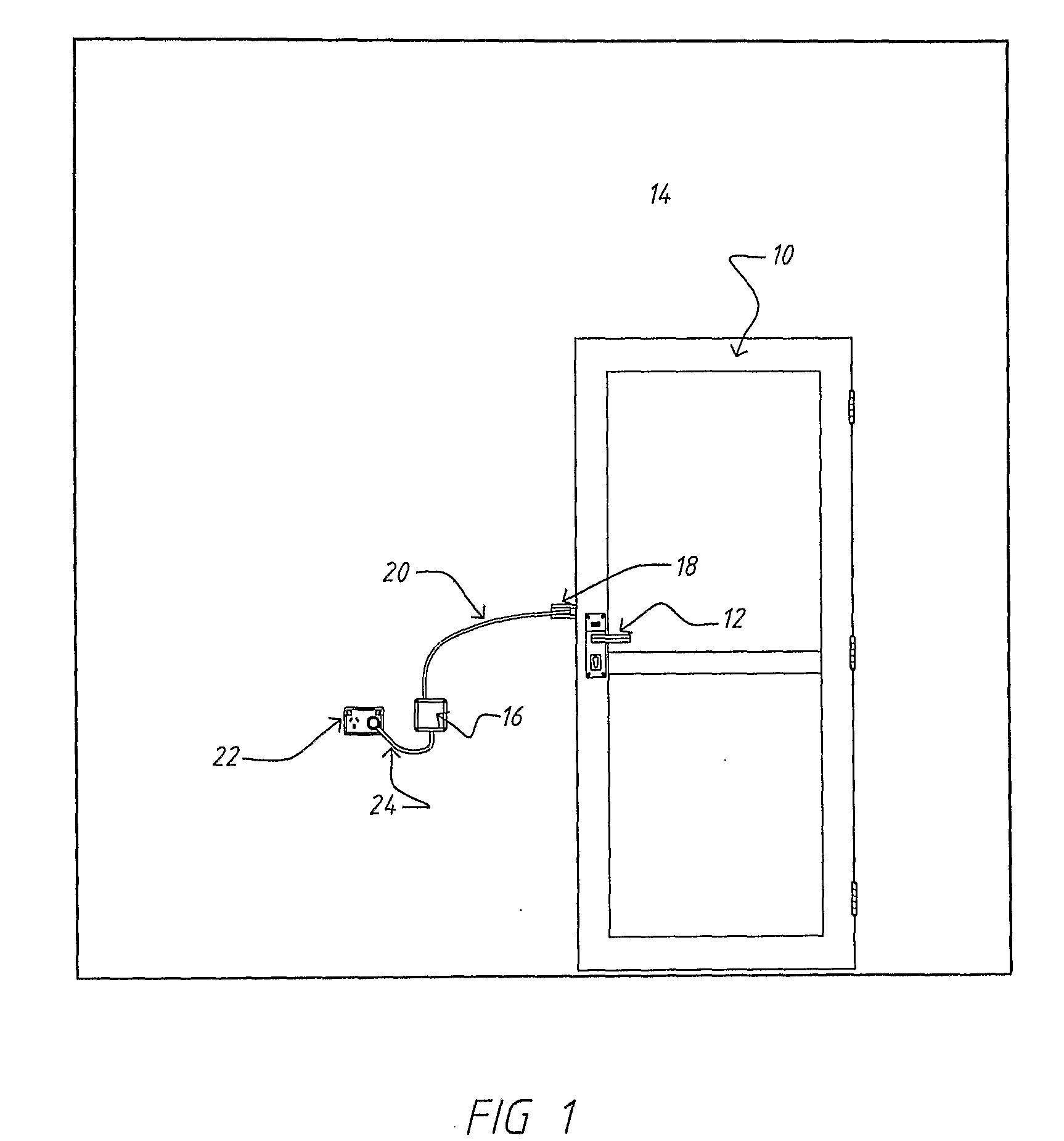
[0045]Turning firstly to FIG. 1, there is shown a door 10 with a lock and latch mechanism 12. The door 10 is mounted in a wall 14. Also shown is a control box 16 which is connected to a power transmitter 18 by a line 20, and to a power source, in the form of a mains socket 22, by a line 24. The control box 16 and the power transmitter 18 form part of an electrically powered lock arrangement that shall be described in more detail below. The control box 16 can alternatively be integrated into the same housing as the power transmitter 18.

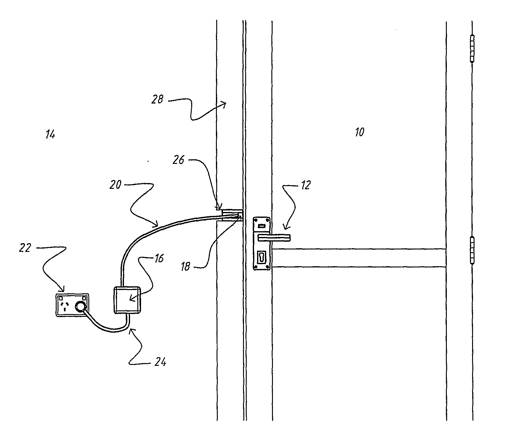
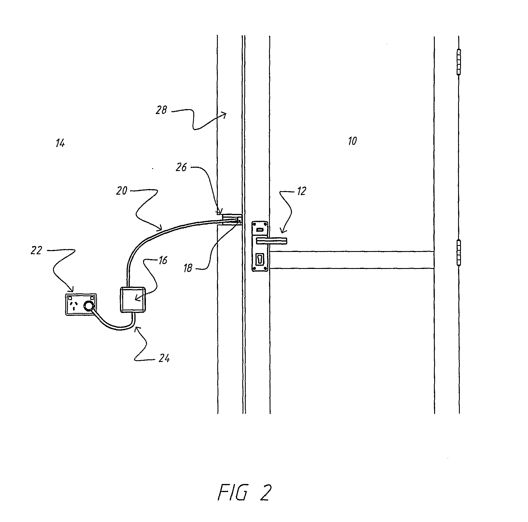
[0046]FIG. 2 is an enlarged, more detailed, view of the components shown in FIG. 1 and, in particular, shows that the power transmitter 18 is positioned within a recess 26 within a door frame 28. The distal end of the power transmitter 18 is substantially flush with the edge of the door frame 28 facing the edge of the door 10 that contains the lock and latch mechanism 12.

[0047]FIG. 3 shows the previously described components in even more detail and als...

second embodiment

[0060]lock arrangement is shown in FIG. 7. This lock arrangement is similar to that previously described except the power transmitter is replaced by a first pair of electrical contacts 100 mounted adjacent the door frame and the power receiver is replaced by a second pair of electrical contact 102 mounted adjacent the door edge. The contacts 100, 102 are mounted such that one or both of them protrude into the air gap between the door frame 28 and the edge of the door 10 and make contact when the door 10 is closed. This allows power, and also control signals, to be transmitted to the door mounted components, similar to that previously described.


PUM


Abstract

A lock arrangement including an electrically powered lock actuator, a power receiver (30) and a power transmitter (18). The electrically powered lock actuator is adapted for mounting in or on a door (10). The power receiver (30) is adapted for mounting in or on the door (10) in electrical connection with the lock actuator. The power transmitter (18) is adapted for mounting adjacent the door (10) and for transmitting power across an air gap to the power receiver (30).

Description

FIELD OF THE INVENTION[0001]The present invention relates generally to a lock arrangement and, more particularly, to an electrically powered lock arrangement and a method of providing power to such a lock arrangement.[0002]The invention has been primarily developed for use in domestic doors. However, the invention is not limited to this particular field of use and is equally suited for any application involving a lock that can be driven by an electrically powered lock actuator.BACKGROUND OF THE INVENTION[0003]Several ways of electrically powering door locks are known. One such way of powering a lock uses a battery to power the lock actuator. The batteries are positioned in the door or in the door furniture that is mounted on the door. A disadvantage of this arrangement is that the lock operation is dependent on battery life and, as a result, battery failure can lead to lock-in, lock-out or loss of security.[0004]An alternative arrangement involves connecting electricity to an actuat...

Claims


Application Information

Patent Timeline
IPC IPC(8): E05B47/00E05B49/04
CPCE05B47/0002E05B47/0012G07C2009/00634E05B2047/0061E05B47/02Y10T70/7062
Inventor LAMBROU, HARRY
Owner GAINSBOROUGH HARDWARE INDS
Features
  • Generate Ideas
  • Intellectual Property
  • Life Sciences
  • Materials
  • Tech Scout
  • Unparalleled Data Quality
  • Higher Quality Content
  • 60% Fewer Hallucinations
Learn More