
Mechanical Properties Testing Device and Method

a mechanical properties and testing device technology, applied in piezoelectric/electrostrictive transducers, instruments, transducer types, etc., can solve the problems of inability to easily relate the properties of small structures and thin films, difficult to measure the mechanical properties of micro-scale samples of materials, and inability to easily obtain mechanical properties

Inactive Publication Date: 2009-12-17
UTAH STATE UNIVERSITY
View PDF5 Cites 7 Cited by
  • Summary
  • Abstract
  • Description
  • Claims
  • Application Information

AI Technical Summary

Problems solved by technology

Measurement of mechanical properties of microscale samples of material, such as thin films, is very difficult due to the small size of the material.
The material properties of small structures and thin films cannot be easily related to the properties of bulk samples because of several reasons.
Therefore, assumption of homogeneity and isotropy is not valid when obtaining the mechanical properties.
In addition, because of comparable size of the structural dimensions and microstructural and defect dimensions, inelastic deformation mechanisms are far different from bulk specimens.
Testing materials at scales smaller than a millimeter is a challenge due to limiting factors such as specimen gripping techniques, the application of small forces, and the ability to measure small strain values.
Therefore, conventional instruments cannot be used to test these properties.
A challenge for creating new microscale testing systems is the design of reliable loading and data capture methods.
Regular strain gages are not applicable due to their large size, and strain measurement techniques such as capacitive gages and digital image correlation are either expensive, hard to use, or not accurate enough.
In addition, digital imaging correlation is a slow and labor intensive process that is not practical for long term fatigue tests.
The Measurement of mechanical properties of micro-scale samples is particularly challenging in fatigue testing of materials since load and displacement are both needed to be monitored for many cycles.

Method used


Image

  • Mechanical Properties Testing Device and Method
  • Mechanical Properties Testing Device and Method
  • Mechanical Properties Testing Device and Method

Examples


Embodiment Construction

[0013]In the following description, numerous specific details are provided for a thorough understanding of specific preferred embodiments. However, those skilled in the art will recognize that embodiments can be practiced without one or more of the specific details, or with other methods, components, materials, etc. In some cases, well-known structures, materials, or operations are not shown or described in detail in order to avoid obscuring aspects of the preferred embodiments. Furthermore, the described features, structures, or characteristics may be combined in any suitable manner in a variety of alternative embodiments. Thus, the following more detailed description of the embodiments of the present invention, as represented in the drawings, is not intended to limit the scope of the invention, but is merely representative of the various embodiments of the invention.

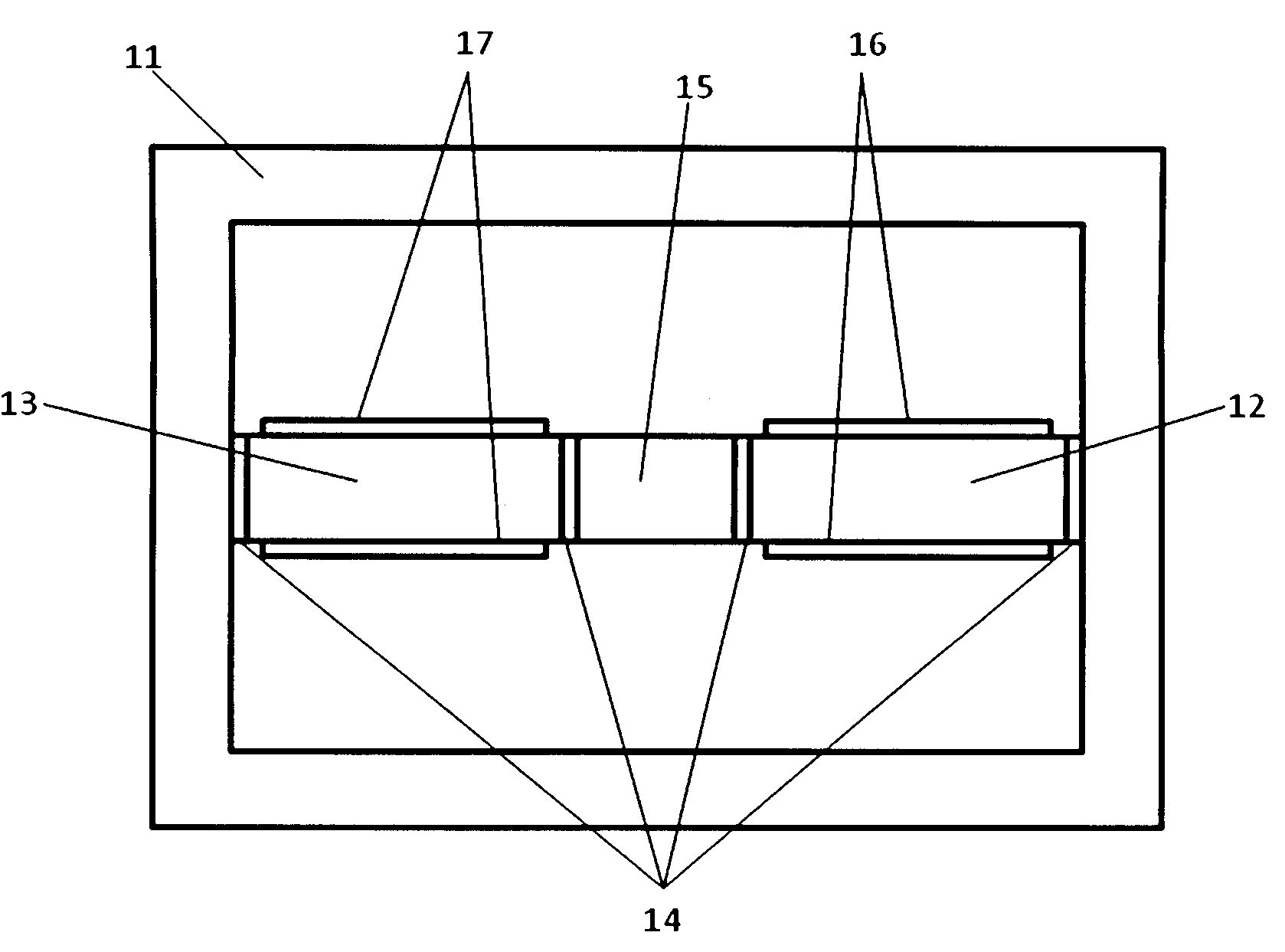
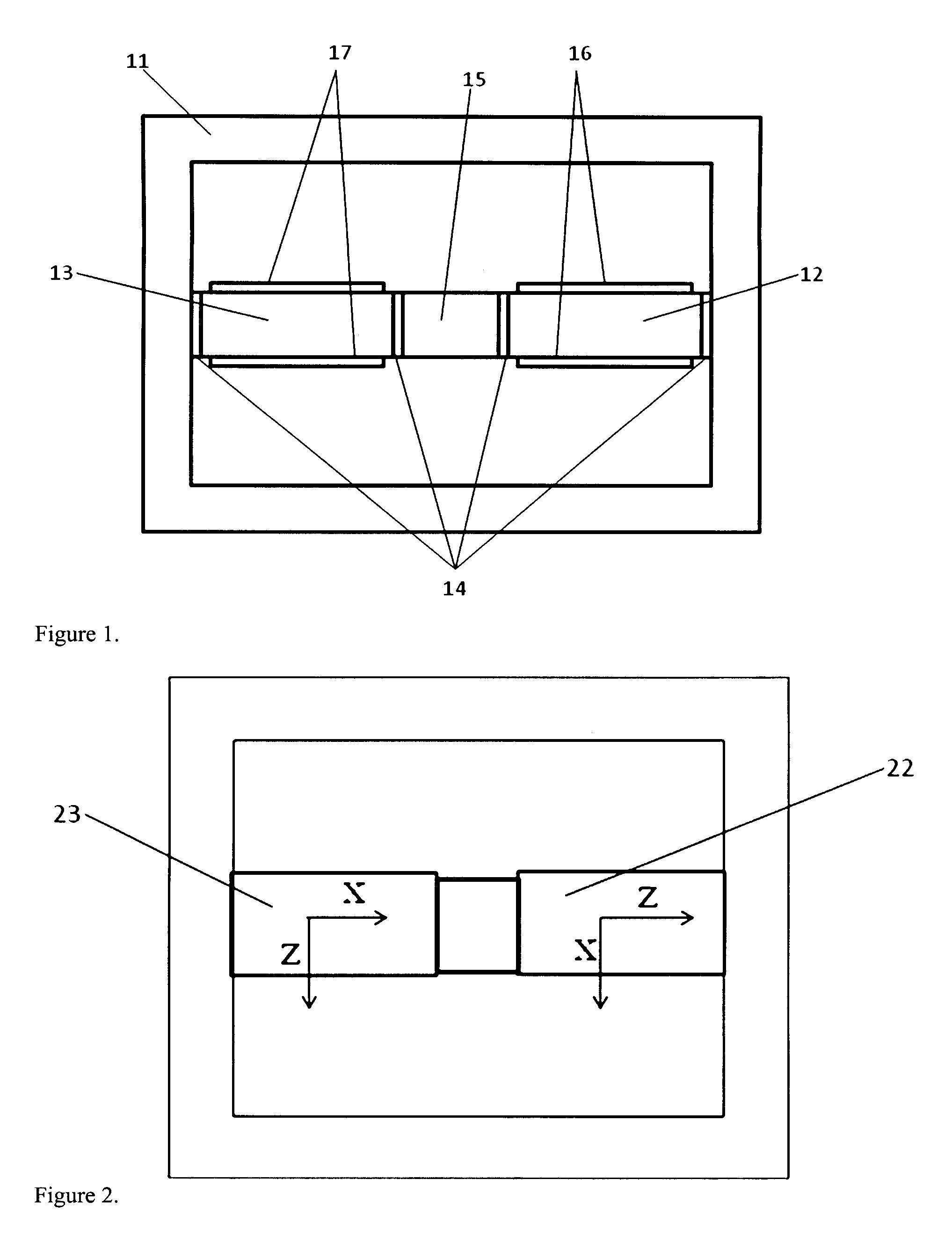
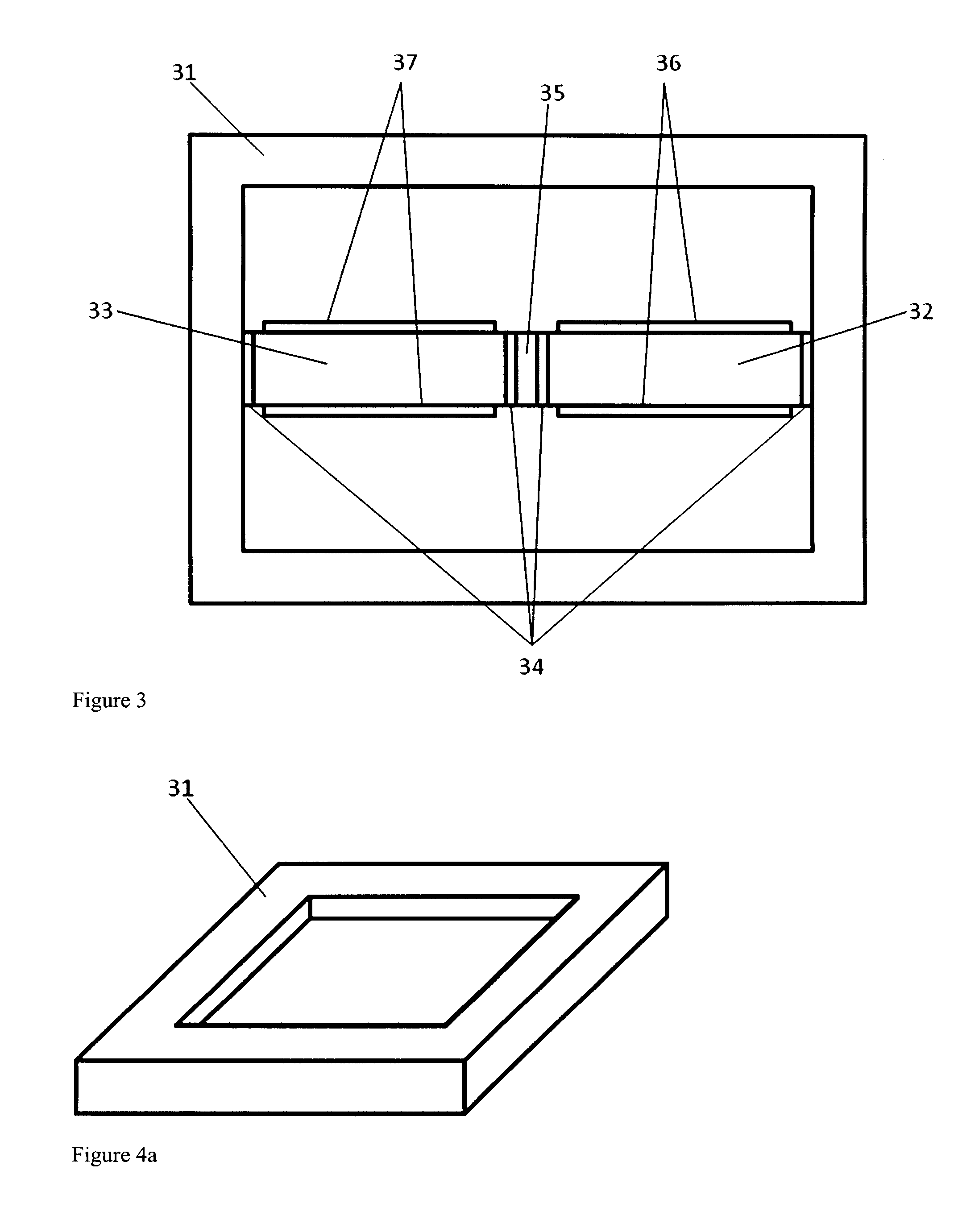
[0014]One embodiment of the mechanical property testing device is shown in FIG. 1. A frame 11 provides a rigid struc...


PUM

PropertyMeasurementUnit
dimensionsaaaaaaaaaa
mechanical characteristicsaaaaaaaaaa
tensileaaaaaaaaaa

Abstract

A mechanical property testing device and method for reliably measuring strain and fatigue characteristics of material specimens is described. An input electrical signal is applied to create an electric field around a first piezoelectric member. The resultant deformation of the first piezoelectric member transfers a force to the specimen being tested which transfers a force to a second piezoelectric member causing deformation. The deformation of the second piezoelectric member generates an output electrical field which is measured. The stress state of the specimen is calculated from fundamental material constants and the measured output electrical field.

Description

RELATED APPLICATIONS[0001]This application claims the benefit of pending U.S. Provisional Patent Application Ser. No. 61 / 073,080 filed on Jun. 17, 2008.FIELD OF THE INVENTION[0002]The present invention relates to a device and method for testing materials, and more particularly, to a piezoelectric device for measuring the mechanical properties of materials.BACKGROUND OF THE INVENTION[0003]Measurement of mechanical properties of microscale samples of material, such as thin films, is very difficult due to the small size of the material. The material properties of small structures and thin films cannot be easily related to the properties of bulk samples because of several reasons. Samples used for bulk mechanical testing generally have dimensions significantly greater than microstructural features, whereas in thin films, the geometrical and microstructural dimensions are on the same order of magnitude. Therefore, assumption of homogeneity and isotropy is not valid when obtaining the mec...

Claims


Application Information

Patent Timeline
Patent Type & Authority Applications(United States)
IPC IPC(8): G01L1/16G01B7/24H01L41/22H10N30/01
CPCG01N3/38G01N2203/0016G01N2203/0051G01N2203/0073Y10T29/49174G01N2203/0623H01L41/331Y10T29/42Y10T29/49147G01N2203/0075H10N30/081
Inventor LADANI, LEILA
Owner UTAH STATE UNIVERSITY
Learn More