Co-Molded Pierceable Stopper and Method for Making the Same

Active Publication Date: 2009-12-17
BECTON DICKINSON & CO
View PDF61 Cites 49 Cited by
  • Summary
  • Abstract
  • Description
  • Claims
  • Application Information

AI Technical Summary

Benefits of technology

[0016]The first molding material may form an external annular skirt and an internal annular skirt, each depending from the top portion, wherein at least a portion of the internal annular skirt defines the target location. The second molding material may be injected from a location which is offset with respect to a longitudinal centerline extending through the target location. The flow channel may extend along the vertical height of an inte

Problems solved by technology

The internal collection cavities of such prior art collection containers are typically straight-walled and provide no features for promoting the flow of drawn blood into the cavity during collection or the flow of blood to the testing instrument during transfer.
Thus a significant amount of the collected blood or specimen sample is caught on the sidewall of the cavity due to surface tension during collection and during transfer.
As a result, a significant amount of dead volume of sample is

Method used


Image

  • Co-Molded Pierceable Stopper and Method for Making the Same
  • Co-Molded Pierceable Stopper and Method for Making the Same
  • Co-Molded Pierceable Stopper and Method for Making the Same

Examples


first embodiment

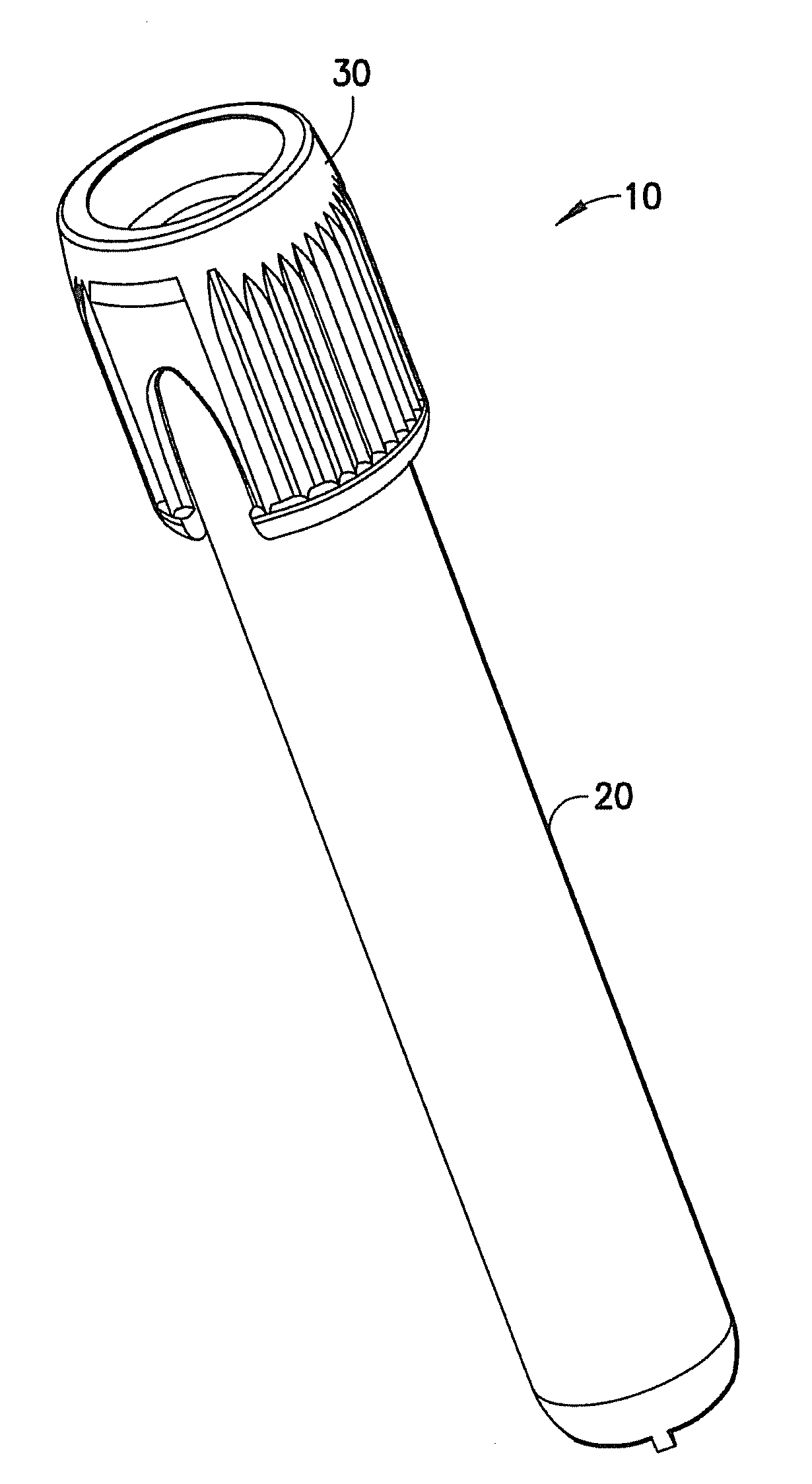
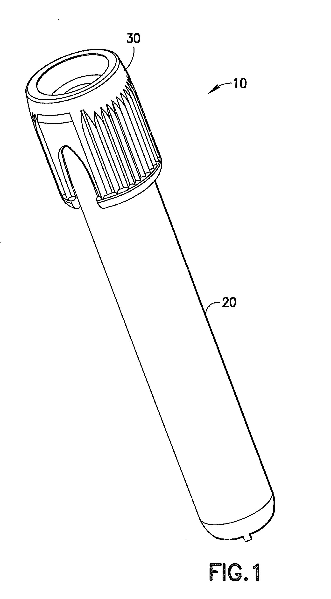
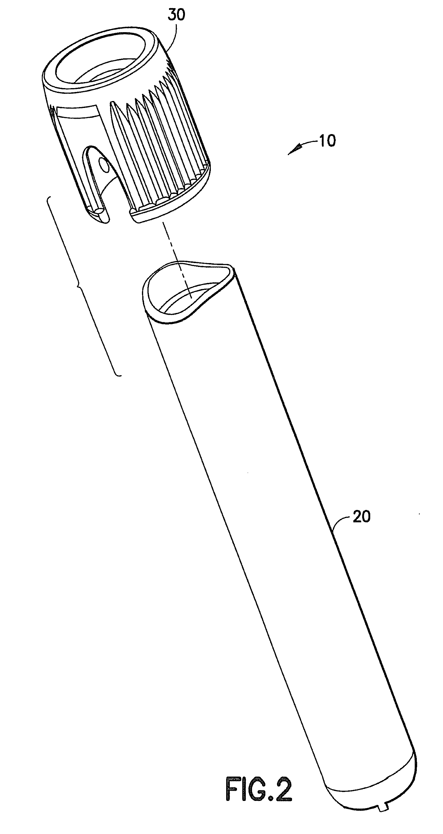
[0082]Referring to FIGS. 1 and 2, a collection device 10 according to the present invention is shown. Collection device 10 includes a collection tube 20 for the collection, storage, and eventual transfer of biological specimens, including blood samples, for purposes of diagnostic testing. A cap assembly 30 is disposed on the collection tube 20 so as to cover and seal the collection tube 20 and any sample contained therein. According to the embodiment shown, cap assembly 30 is removably disposed and attached to the collection tube 20 after collection of the sample contained therein.

[0083]The collection tube 20 may be a biological specimen collection container for proteomics, molecular diagnostics, chemistry sampling, blood or other bodily fluid collection, coagulation sampling, hematology sampling, and the like. In one embodiment, the collection tube 20 can be particularly suited for receipt and storage of a bodily fluid specimen. In a further embodiment, the collection tube 20 is pa...

third embodiment

[0117]Referring to FIGS. 18 and 19, a collection device 80 according to the present invention is shown. Collection device 80 includes a collection tube 85 for the collection, storage, and eventual transfer of biological specimens, including blood samples, for purposes of diagnostic testing. A cap assembly 90 is disposed on the collection tube 85 so as to cover and seal the collection tube 85 and any sample contained therein. According to the embodiment shown, cap assembly 90 is removably disposed and attached to the collection tube 85 after collection of the sample contained therein.

[0118]As shown in FIGS. 20 and 23, collection tube 85 is a microtube suited for capillary collection of blood samples having exterior dimensions of 13×75 mm so as to be compatible with standard testing instruments. Collection tube 85 is injection molded from suitable plastic or composite material as is known to be suitable by those of ordinary skill in the art. It is also contemplated herein that althoug...

fourth embodiment

[0138]With reference to FIGS. 30-43 and 48 there is shown a collection device 1000 having a cap assembly 100 according to the invention. The collection device 1000 includes a collection tube 104, which is preferably tubular in shape, comprising a closed bottom 105, an open top portion 102, and a sidewall 107 extending circumferentially between the open top portion 102 and the closed bottom 105. The collection tube 104 is configured for receiving a specimen sample therein, such as blood. According to one embodiment, the collection tube 104 may include at least one capillary channel as discussed in detail above in relation to FIGS. 3, 5-6, 11, and 20. FIGS. 44 and 45 show a method of co-molding the cap assembly of FIGS. 30-43 and 48. The method of co-molding the cap assembly 100 according to the present invention is particularly advantageous as it allows for consistent molding of the pierceable portion, i.e., septum, within the cap assembly.

[0139]With reference to FIGS. 30 and 48, a c...


PUM

PropertyMeasurementUnit
Angleaaaaaaaaaa
Distanceaaaaaaaaaa
Thicknessaaaaaaaaaa

Abstract

A closure and method of making a closure are disclosed. The closure includes a cap body having a top portion and an opening extending therethrough defining a cavity in communication with said opening. A flow channel is defined within a portion of the cap body having an inlet and an outlet. A stopper is disposed within the cavity adjacent the outlet of the flow channel. The stopper is formed from a material adapted for flowing through the flow channel to form a pierceable portion, with at least one of the cap body and the stopper configured for closing a container.

Description

CROSS REFERENCE TO RELATED APPLICATION[0001]This application claims priority to U.S. Provisional Patent Application No. 61 / 033,966, filed Mar. 5, 2008, entitled “Device for Capillary Collection of Blood Samples”, the entire disclosure of which is herein incorporated by reference.BACKGROUND OF THE INVENTION[0002]1. Field of the Invention[0003]The present invention relates to a device for the collection, storage, and transfer of a blood or specimen sample obtained from a patient for medical diagnostic testing. More specifically, the present invention relates to a device for capillary collection of blood samples from a skin surface of the patient. The device includes a collection tube having a lip feature surrounding a top opening of the tube suitable for collecting samples from a skin surface. The device also includes a cap assembly having a stopper for closing and sealing the tube after the blood or specimen sample has been collected. The stopper incorporates space elimination featur...

Claims


Application Information

Patent Timeline
IPC IPC(8): G01N1/10B65D51/18B29C45/16
CPCA61B5/1411B65D51/002G01N1/00B29D99/0096B65D2221/00A61B5/150022A61B5/15003A61B5/150259A61B5/150274A61B5/150351A61B5/150396A61B5/150511A61B5/154
Inventor BLEKHER, ALEXWILKINSON, BRADLEY M.RUSS, CRAIG OWEN
Owner BECTON DICKINSON & CO
Why Eureka
Try Eureka