Steering device

a technology of a steering device and a nut, which is applied in the direction of mechanical equipment, transportation and packaging, etc., can solve the problems that the manufacturing cost of the feed screw mechanism cannot be reduced further, and the backlash adjustment must be performed, so as to reduce the manufacturing cost of the feed screw mechanism, the effect of reducing the backlash and avoiding the feed nu

Inactive Publication Date: 2009-12-17
NSK LTD
View PDF27 Cites 24 Cited by
  • Summary
  • Abstract
  • Description
  • Claims
  • Application Information

AI Technical Summary

Benefits of technology

[0016]In the steering device and feed screw mechanism according to this invention, the feed nut is formed from three nuts: a middle feed nut disposed in a middle position with respect to the axial direction of the feed screw shaft and end portion feed nuts respectively disposed on both axial end positions of the middle feed nut. A resilient member is interposed between the middle feed nut and the end portion feed nuts. The resilient member exerts an enlarging biasing force with respect to the axial interval between the middle feed nut and the end portion feed nuts in order to eliminate backlash with the feed nut.
[0017]Thus manufacturing costs of a feed screw mechanism can be reduced and rigidity improved by using a simple backlash adjustment operation to ensure elimination of backlash even when the precision of the screw ridge of the feed screw shaft and the feed nut is not high.
[0018]Furthermore even if the screw ridge of the feed screw shaft and the feed nut becomes worn, since backlash can be eliminated by ongoing wear, the durability of the feed screw mechanism is improved

Problems solved by technology

Consequently the manufacturing costs of the feed screw mechanism cannot be reduced Furthermore if the screw ridge of the feed screw shaft and the feed nut becomes worn, backlash adjustment must be performed again.

Method used


Image

  • Steering device
  • Steering device
  • Steering device

Examples


Embodiment Construction

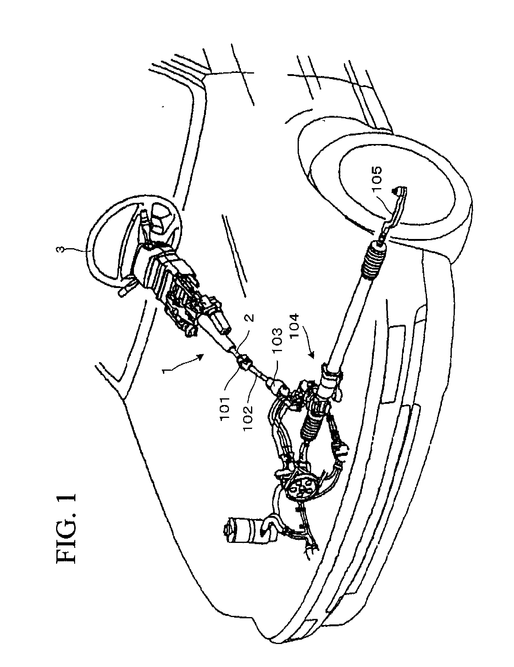
[0095]FIG. 1 an overall perspective view of a steering device 1 according to this invention mounted in a vehicle. As shown in FIG. 1, the steering device 1 is pivoted to rotate freely on a steering shaft 2. A steering wheel 3 is attached to the right end (towards vehicle rear) of the steering shaft 2. A middle shaft 102 is connected via a universal joint 101 to the left end (towards vehicle front) of the steering shaft 2.

[0096]A universal joint 103 is connected to the left end of the middle shaft 102. A steering gear 104 composed of a rack and pinion mechanism for example is connected to the universal joint 103.

[0097]When a driver rotates the steering wheel 3, torque is transmitted to the steering gear 104 via the steering shaft 2, the universal joint 101, the middle shaft 102, and the universal joint 103. The rack and pinion mechanism displaces a tie rod 105 and it is possible to vary the steering angle of the vehicle wheels.

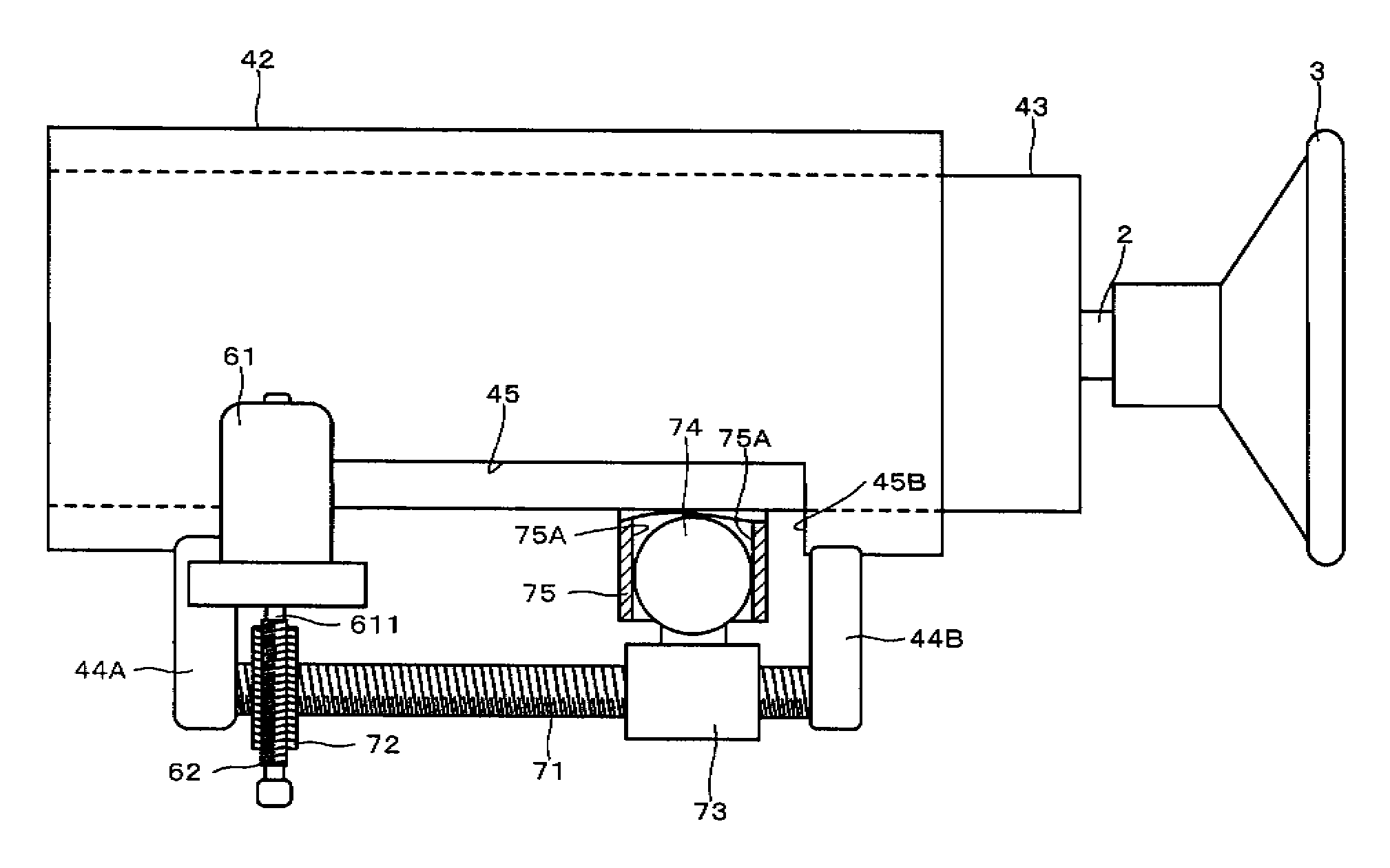
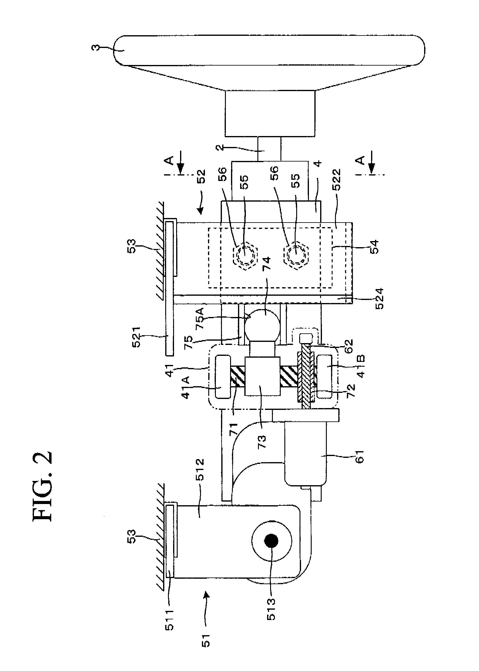
[0098]FIG. 2 is a schematic view of the main components i...


PUM


Abstract

Provided are a steering device and a feed screw mechanism. The steering device is made so easy in the adjusting work of a backlash that it can eliminate the backlash reliably, even if the precision of the thread of a feed thread shaft or a feed nut is poor, thereby to improve the rigidity and to reduce the manufacturing cost of the feed screw mechanism. An upper-side end portion feed nut is urged upward of FIG. 8 by an upper-side disc spring so that an upper-side flank face of the thread ridge of the upper-side end portion fee nut is brought into close contact with the lower-side flank face of the thread ridge of a feed screw shaft. On the other hand, a lower-side end portion feed nut is urged downward of FIG. 8 by a lower-side disc spring so that a lower-side flank face of the thread ridge of the lower-side end portion fee nut is brought into close contact with the upper-side flank face of the thread ridge of the feed screw shaft. As a result, a feed nut and the feed screw shaft are cleared of the backlashes in the two upward and downward directions of FIG. 8.

Description

FIELD OF THE INVENTION[0001]The present invention relates to a steering device and more particularly to a feed screw mechanism and a steering device enabling adjustment of a telescopic position and a tilt position of a steering wheel using the feed motion of the feed screw mechanism.BACKGROUND OF THE INVENTION[0002]It is necessary to adjust a tilt position or a telescopic position of a steering wheel in response to the posture or build of a driver. A steering device is known which adjusts the tilt position or telescopic position using a feed screw mechanism using an electric motor to rotate a feed screw shaft which performs translatory motion with respect to a feed nut which is threadably engaged with the feed screw shaft.[0003]As shown in Patent Literature 1, the conventional feed screw mechanism used in this type of steering device eliminates backlash between the feed screw shaft and the feed nut in order to produce a smooth feed motion.[0004]FIG. 9 shows a feed screw mechanism ac...

Claims


Application Information

Patent Timeline
Patent Type & Authority Applications(United States)
IPC IPC(8): F16H25/22B62D1/185
CPCB62D1/181Y10T74/18728F16H25/2006
Inventor TOMARU, MASAKITOMARU, YUICHIYONEZAWA, KOUHEIMINAMIGATA, TAKAHIRONAGAI, KOJI
Owner NSK LTD
Why Eureka
Try Eureka