Pneumatic Tire

a technology of pneumatic tires and wet properties, applied in the field of pneumatic tires, can solve the problems of deterioration of productivity and increase in costs, difficulty in sufficiently showing the original effect, and reducing the effect of improving the adhesion and wet properties of the tread by silica compounding, etc., to achieve excellent rolling resistance and improve adhesion.

Inactive Publication Date: 2009-12-17
TOYO TIRE & RUBBER CO LTD
View PDF25 Cites 21 Cited by
  • Summary
  • Abstract
  • Description
  • Claims
  • Application Information

AI Technical Summary

Benefits of technology

[0016]By using the cushion rubber disposed on the tire inside face side of the side wall as a conducting path in order to improve adhesion between different kinds of rubbers, such as a side wall rubber, a carcass and a rim strip rubber, the pneumatic tire of the present invention can provide a tire having conductivity while additionally having excellent rolling resistance and wet properties due to silica compounding, that can be manufactured by the conventional process without requiring any special tire manufacturing step as disclosed in the prior art, and without needing addition of material members and process steps, and can eliminate problems such as noises, adverse influence to electronic parts, and short-circuit, due to static electricity charged in vehicles using a nonconductive tire of silica compounding or the like.

Problems solved by technology

However, the technology of Patent Document 1 is that improvement effects on rolling resistance and wet properties of a tread by silica compounding are decreased by arranging the above-described conductive thin film containing carbon black, and it is difficult to sufficiently exhibit the original effect.
Furthermore, from that the conductive thin film containing carbon black is arranged on the outer surfaces of a tread and a sidewall, additional material members and process steps are required, and deterioration of productivity and increase in costs are predicted.
Thus, it is difficult to say that such a tire has a structure that is easily produced, and decrease in productivity is predicted.

Method used


Image

  • Pneumatic Tire
  • Pneumatic Tire
  • Pneumatic Tire

Examples


first embodiment

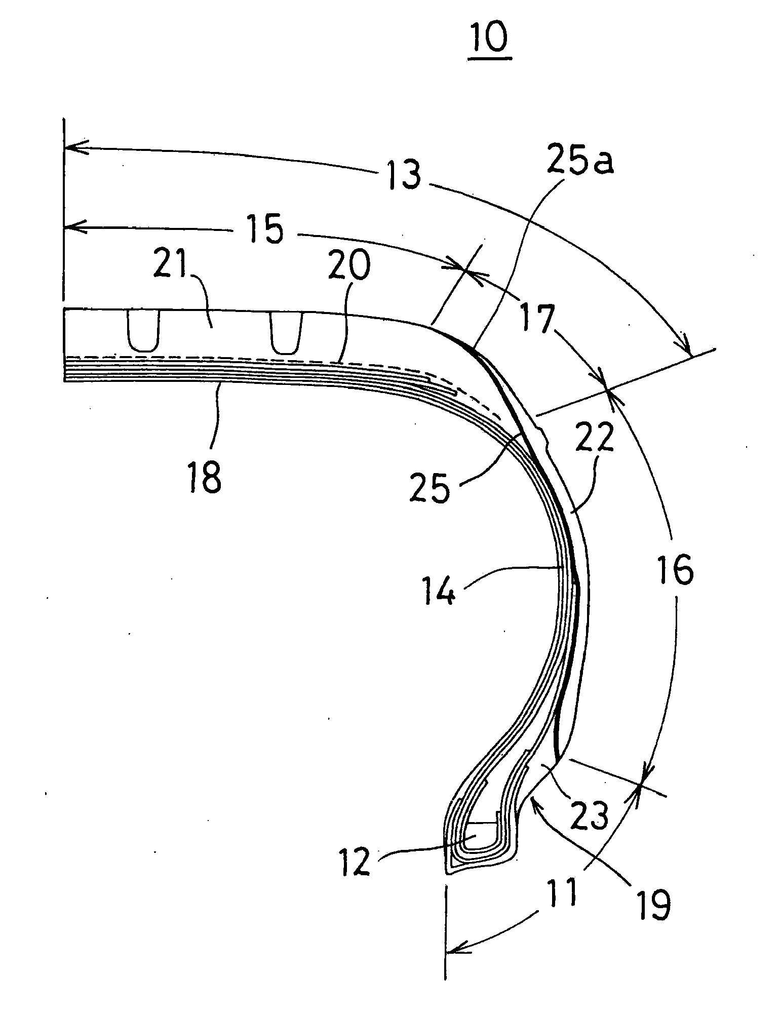
[0018]FIG. 1 is a semi-sectional view showing a pneumatic tire of a first embodiment.

[0019]The pneumatic tire (hereinafter, a pneumatic tire is simply referred to as a “tire”) 10 comprises a pair of bead parts 11 to be mounted on a rim, a side wall part 16 extending outward in a radial direction of the tire from the bead part 11, and a tread part 13 ground-contacted to road surface laid between the side wall parts 16, 16, and the tread part 13 comprises a crown part 15 constituting a main ground contact part at the central portion in a width direction of the tire, and a shoulder part 17 positioned at both sides of the tread part 13 to form a ground contact edge region and being continuous to the side wall part 16.

[0020]The tire 10 has a rim strip 19 contacting with a flange of a rim provided outward in an axial direction of the tire of the bead part 1, and the lower edge of the side wall part 16 is contacted with the rim strip 19 by overlapping on the upper edge thereof.

[0021]The ti...

second embodiment

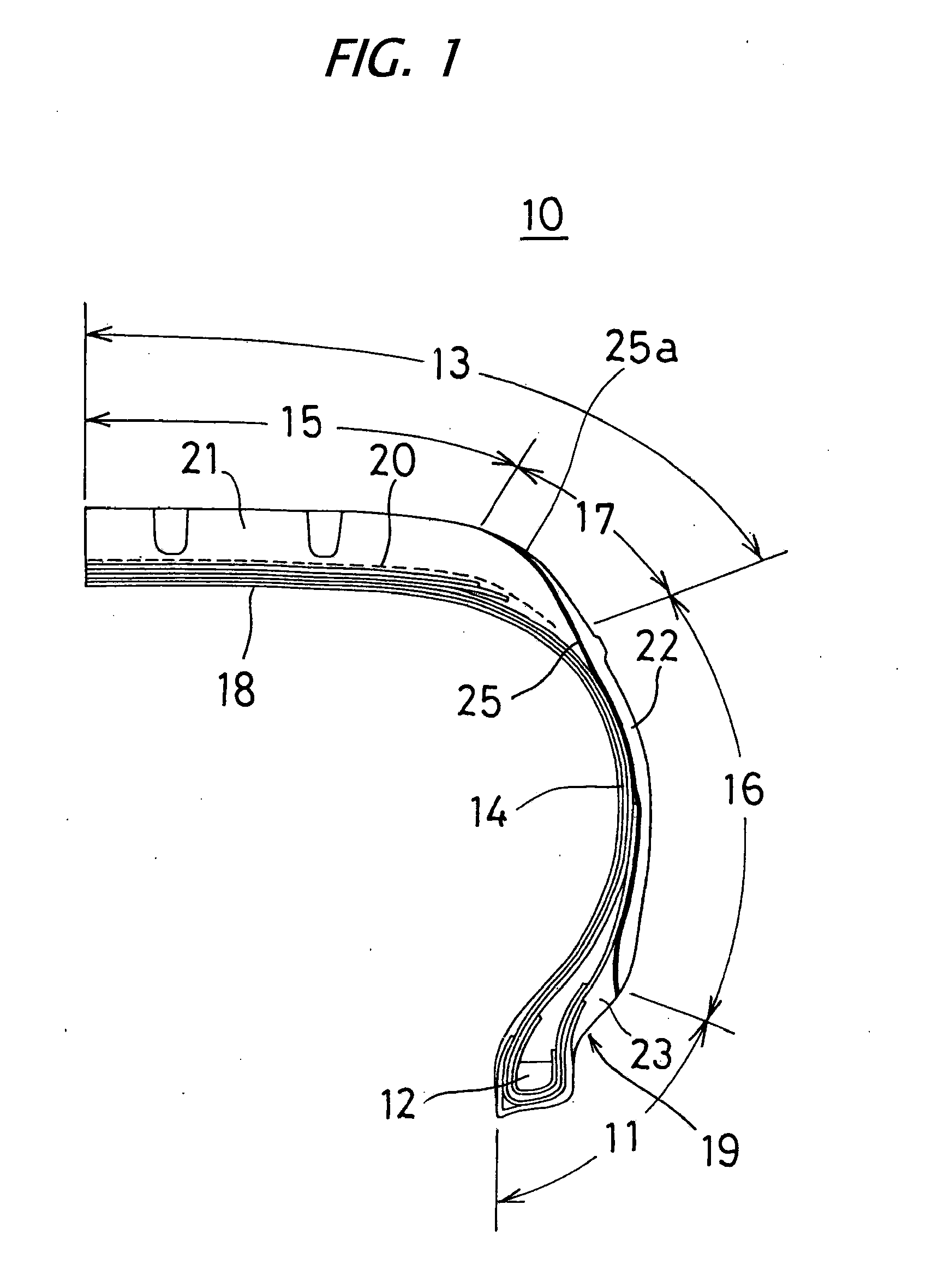
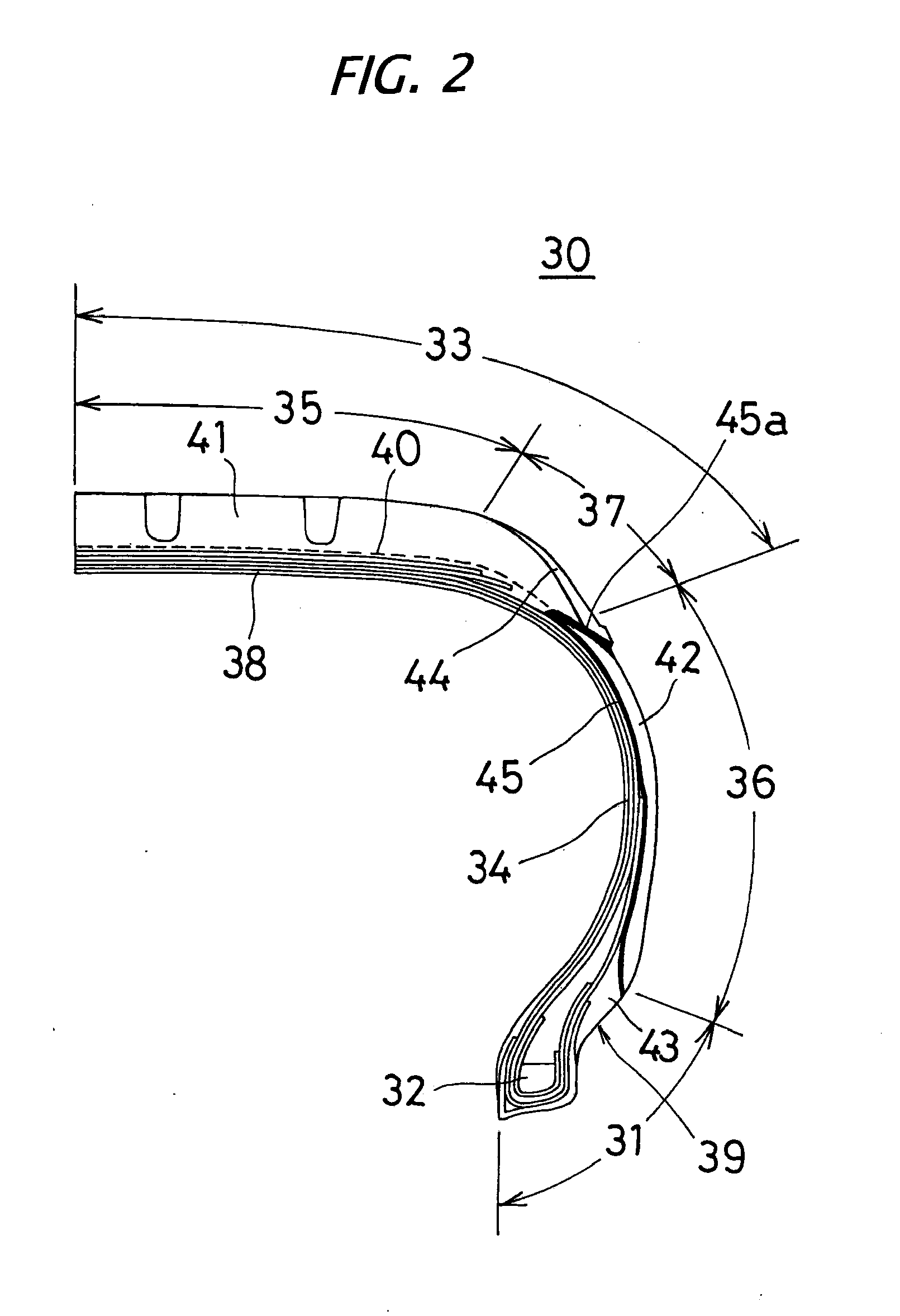
[0055]FIG. 2 is a semi-sectional view showing a pneumatic tire 30 of a second embodiment.

[0056]The pneumatic tire 30 comprises a pair of bead parts 31 to be mounted on a rim, a side wall part 36 extending outward in radial direction of the tire from the bead part 31, and a tread part 33 ground-contacted to road surface laid between the side wall parts 36, 36, and the tread part 33 comprises a crown part 35 constituting a main ground contact part at the central portion in a width direction of the tire, and a shoulder part 37 positioned at both sides of the tread part 33 to form a ground contact edge region and being continuous to the side wall part 36.

[0057]The tire 30 has a rim strip 39 contacting with a flange of a rim arranged outward in a radial direction of the bead part 31, and the lower edge of the side wall part 36 is contacted with the rim strip 39 by overlapping on the upper edge thereof.

[0058]The tire 30 has a tread-over-side wall (TOS) structure in which the both edges of...

third embodiment

[0087]A third embodiment is an embodiment that a formation method of a side wall cushion rubber is changed, and the present embodiment is described using the sectional view of the tire 10 of FIG. 1.

[0088]Conventionally, the side wall cushion rubber 25 of the first embodiment is generally obtained by a method in which the sheet-like cushion rubber 25 having a thickness of about 0.2 to 1.0 mm extruded from a rubber extruding machine is adhered to the tire inside face side of the side wall rubber 22 separately extrusion molded, following the extrusion molding of the cushion rubber 25, thereby forming a cushion layer.

[0089]Furthermore, a cushion rubber sheet obtained by rolling processing by calendaring or the like may be adhered to the tire inside face side of the side wall rubber 22 previously extrusion molded to integrate with the side wall rubber.

[0090]However, the conventional method requires that cushion rubbers having different width and thickness are subjected to extrusion moldi...


PUM


Abstract

A pneumatic tire that can be manufactured according to the conventional method without requiring special tire manufacturing steps and without needing addition of material members and production steps, has excellent rolling resistance and wet properties, and has conductivity. The pneumatic tire 10 has a sheet-like cushion rubber 25 having a thickness of 1 mm or less, disposed on a tire inside face side of a side wall rubber, the cushion rubber 25 is in contact with a rim strip 19 and exposed to a surface of a ground contact edge region of a tread part 13 through a side wall part 16, and is characterized in that on the circumference of unilateral or bilateral side portions of the tire 10, the rim strip 19 and the cushion rubber 25 are formed into a continuous conductive path by a conductive rubber material, only the conductive path is used as a conducting path of the tire 10, and members other than the conducting path are selected and used from a conductive rubber material or a nonconductive rubber material.

Description

TECHNICAL FIELD[0001]The present invention relates to a pneumatic tire. More particularly, the invention relates to a pneumatic tire manufactured by the conventional process, that has a tread of silica compounding or the like, improves rolling resistance and wet properties of a tire, and can discharge static electricity charged in vehicles to road surface.BACKGROUND ART[0002]To improve rolling resistance and running performance (wet properties) on wet road surface of a pneumatic tire, the technology of compounding silica with a rubber composition of a tread as a reinforcing agent in place of the conventional carbon black is known. With this silica compounding technology, static electricity charged in vehicles gives rise to the problems that discharge phenomenon is generated when a tire passes on manholes and the like, resulting in radio noise, adverse influence to electronic circuit parts, generation of short-circuit, and the like.[0003]Conventionally, to solve those problems, the t...

Claims


Application Information

Patent Timeline
Patent Type & Authority Applications(United States)
IPC IPC(8): B60C19/08
CPCB60C19/08B60C13/04
Inventor NAKAMURA, NORIHIKO
Owner TOYO TIRE & RUBBER CO LTD
Why Eureka
Try Eureka