

Drinking fitment
a technology for drinking bottles and fittings, applied in the direction of closures, caps, closure stoppers, etc., can solve the problems of mouthpiece exposed, cost and weight of the closure and container, cost, complexity and efficiency of the mold needed to make the closure, etc., and achieve low cost sports caps. , easy assembly, reliable leak-free seal
- Summary
- Abstract
- Description
- Claims
- Application Information
AI Technical Summary
Benefits of technology
Problems solved by technology
Method used
Image

Examples
second embodiment
[0052]A second embodiment of the closure is shown in FIGS. 5 and 6 (wherein like reference numerals are used for like parts). This design is the same as the first embodiment except for the coupling part 50 at the base of the nozzle 6, the base of the outer shell 4 and the method of assembly.
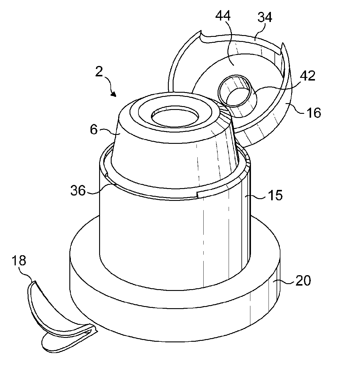
[0053]In this embodiment the overcap 16 is connected to the base 14 by means of a tamper band 18. The base 14 has a skirt 20 that terminates in a lip 22 adapted to snap fit over an outwardly projecting bead 24 at a rim of a container neck 10.
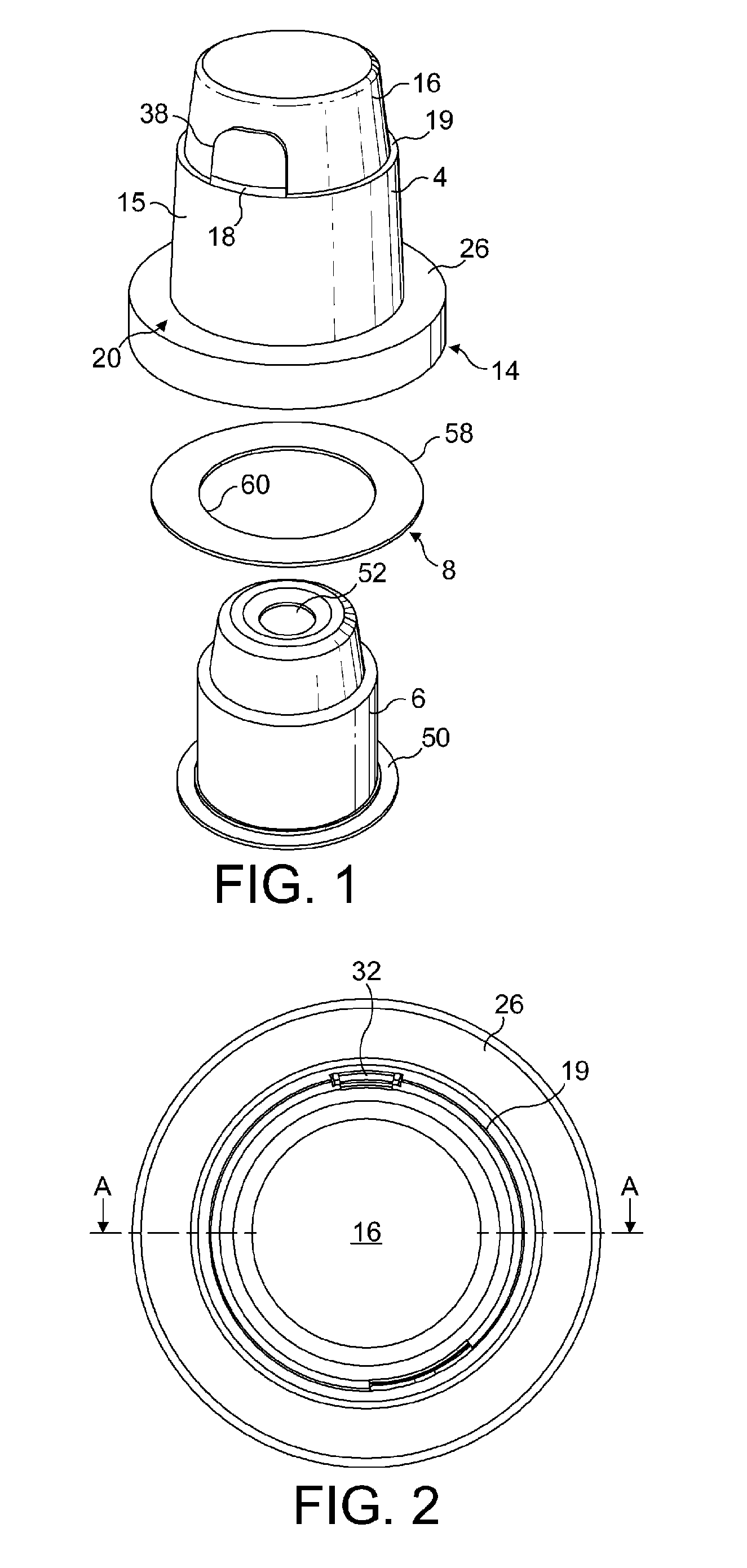
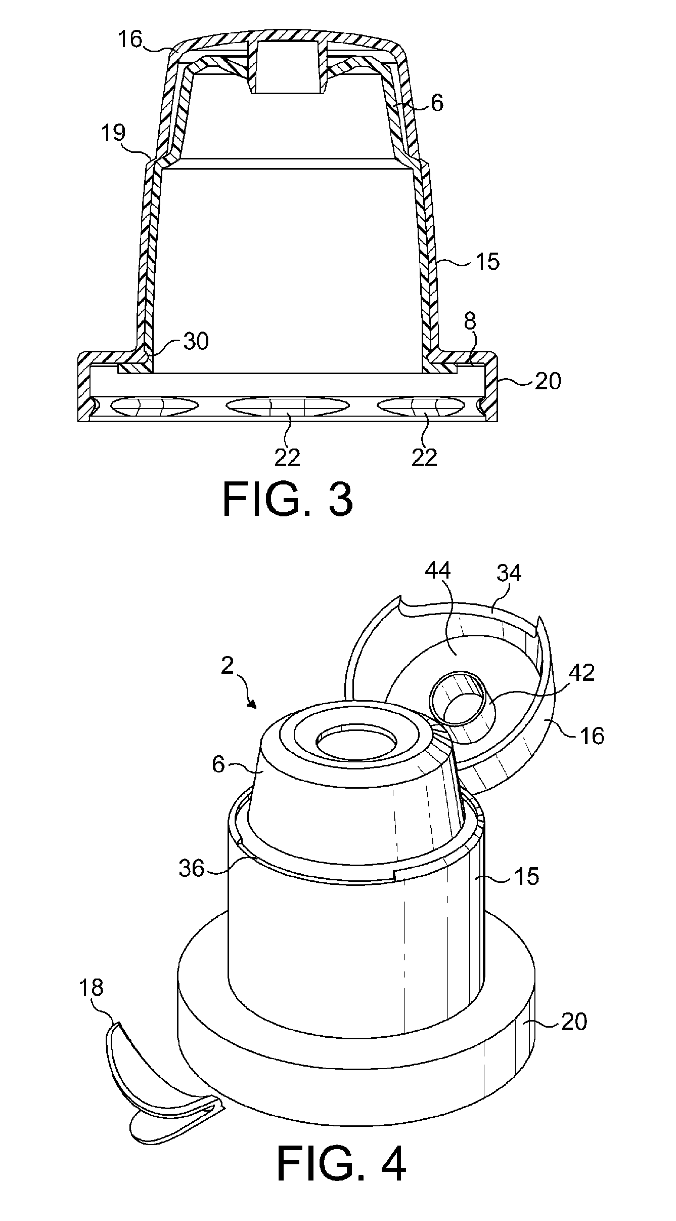
[0054]The skirt 20 depends from an annular base plate 26 which covers an outer part of the opening of the neck 10. In this embodiment, the plate 26 is stepped to define an internal recess 28. Although an annular base plate of uniform width is illustrated in FIG. 5, it will be appreciated that a circular opening 30 in the base plate that receives the nozzle 6 may be offset to one side so that it is easier for the consumer to reach.
[0055]A hinge formation 32 pe...
third embodiment
[0062]A third embodiment of the closure is shown in FIG. 7 (wherein like reference numerals are used for like parts). This design is similar to the first embodiment except that the nozzle 6 is not centred within the base 14 but offset and a new sealing valve structure is shown on the coupling part 50. An alternative nozzle profile is shown and the overcap has a second outer valve seal 82 concentric with valve seal 42 to engage with an outer surface of the nozzle 6. This embodiment is assembled in the same way as the first embodiment.
[0063]The coupling part 50 terminates in a depending valve wall 80 that is designed to push fit into the open neck 10 of the container 12. This is particularly advantageous when the closure is being used on a container containing pressurised contents such as carbonated drinks. In this situation, the pressure will act to force the valve wall 80 against the neck holding the closure in position.
[0064]In order to enable the outer shell 4 to be moulded in one...
fourth embodiment
[0065]The closure of FIG. 8 differs from the first embodiment only in that it is designed to fit in a conventional manner on a standard pre-form PCO neck finish in any of the popular sizes such as 28 mm, 30 mm, 33 mm, 35 mm, 38 mm and 43 mm or 45 mm. The skirt 20 is provided with an internal screw thread 70 to co-operate with the external threads on the standard neck. The lower edge of the skirt 20 may be connected to a tamper evident strip 72 by breakable bridges 74. This embodiment of the closure can be used without the need for any modification of existing bottles.
Variations
[0066]Although a separate hinge 32 has been described, it will be possible to create a hinge by retaining part of the tamper band 18 as a permanent connection between the overcap and base.
[0067]The tamper element 18 could also be omitted and the lower edge of the overcap 16 joined to the base by a frangible region. The peak 40 would then need to be sufficiently substantial to enable the user to use it to initi...
PUM
 Abstract
Description
Claims
Application Information