Heating Unit, Tire Heating Apparatus, and Method for Remodeling Tire Mold

a tire heating and tire heating technology, applied in the field of heating units and tire heating apparatuses, can solve the problems of inferior heat efficiency of steam heating, and achieve the effects of improving heating efficiency, high thermal diffusivity, and efficient heating of tires

Inactive Publication Date: 2009-12-17
KOBE STEEL LTD
View PDF14 Cites 16 Cited by
  • Summary
  • Abstract
  • Description
  • Claims
  • Application Information

AI Technical Summary

Benefits of technology

[0019]When a tire mold for steam heating is diverted and heated by a method other than steam heating, for example, by a method adapted to induction-heat a metal to be heated by an induction heating coil, an annular hole of the tire mold which is used as a steam flow passage becomes a factor for inhibiting improvement in heating efficiency, if the annular hole is left as it is or is filled with air, since thermal diffusion is inhibited by the annular hole part of the tire mold. Therefore, by adapting the structure as described above, heat can be rapidly diffused within the tire mold to efficiently heat the tire, compared with the case in which the annular hole is fil

Problems solved by technology

However, the heating using steam is inferior in heat efficiency since the thermal energy of the steam i

Method used


Image

  • Heating Unit, Tire Heating Apparatus, and Method for Remodeling Tire Mold
  • Heating Unit, Tire Heating Apparatus, and Method for Remodeling Tire Mold
  • Heating Unit, Tire Heating Apparatus, and Method for Remodeling Tire Mold

Examples


first embodiment

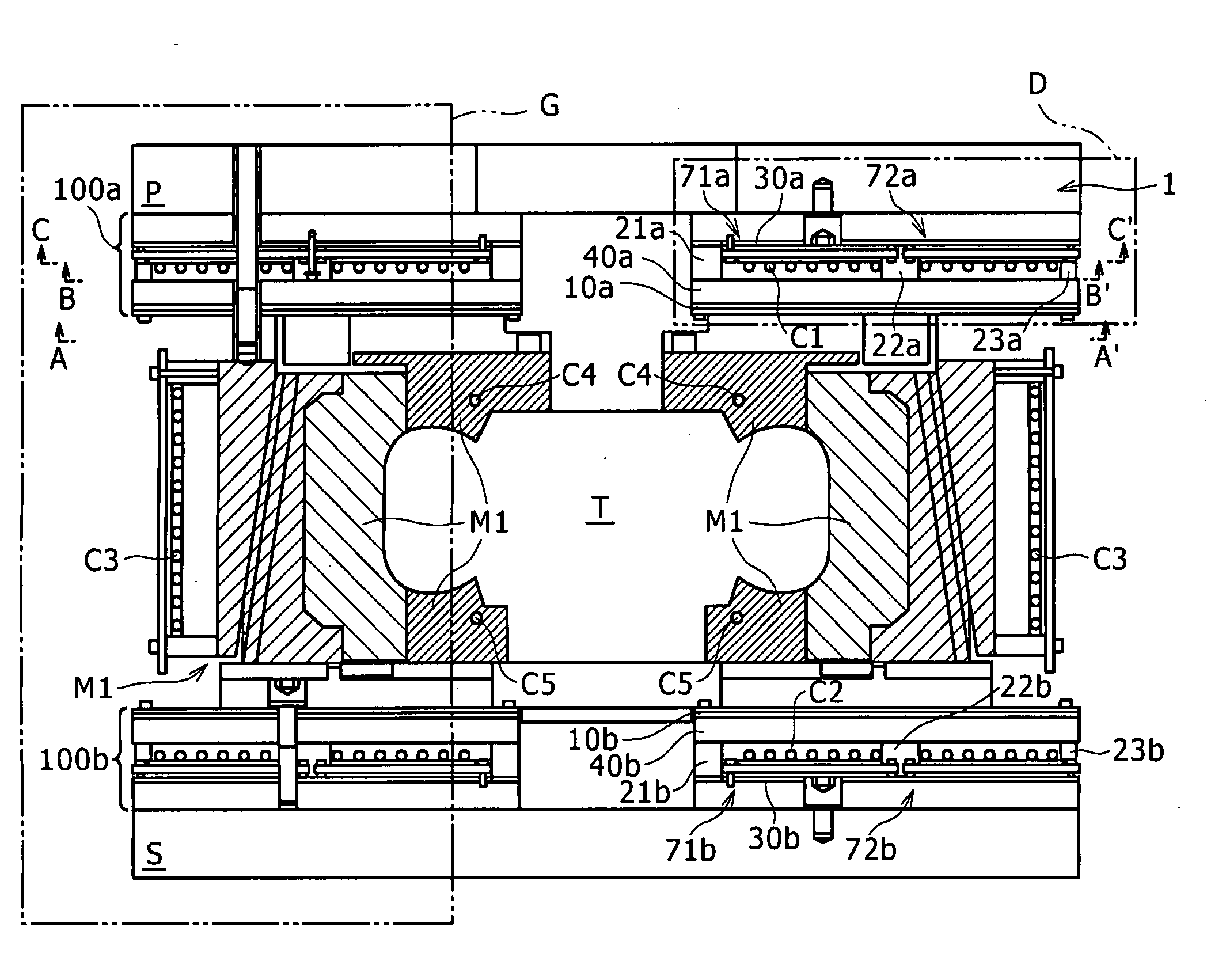
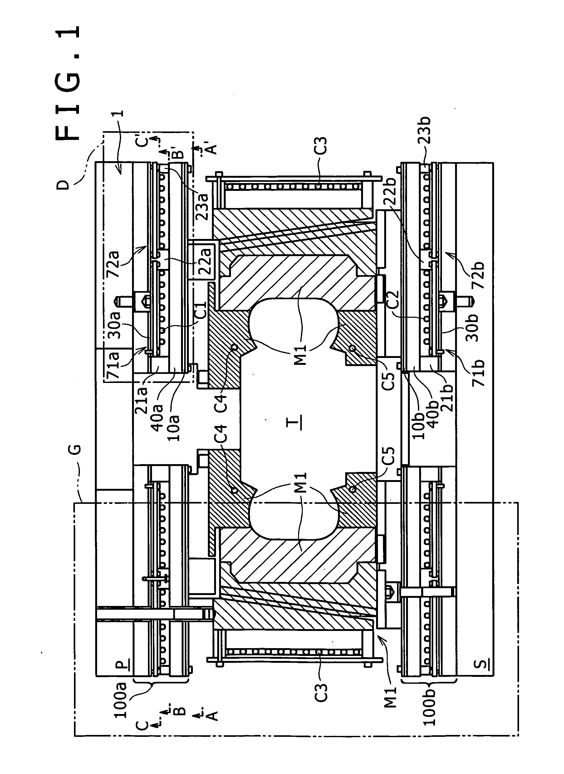
[0049]The entire structure of a tire heating apparatus according to the first embodiment will be described in reference to FIG. 1. FIG. 1 is a schematic side sectional view of the tire heating apparatus according to this embodiment, which shows the entire structure of this embodiment. In FIG. 1, although the mold part is shown by diagonal lines showing a section thereof, diagonal lines are omitted for the heating unit part since the detail thereof is shown in the enlarged view of FIG. 3. In this embodiment, the heating unit of the prevent invention is used as a part of a heating apparatus of a tire vulcanizer.

[0050]A tire heating apparatus 1 comprises, as shown in FIG. 1, a tire mold M1, two heating units 100a and 100b disposed vertically opposite each other to hold the tire mold M1 from both the upper side and lower side thereof, an upper platen support P located at the top of the upper heating unit 100a, and a lower platen support S as a base part located at the bottom of the lowe...

example 1

[0074]Results of heating test carried out using the tire heating apparatus 1 are shown. The test was carried out in the following condition. Since the same condition was adapted to the upper and lower heating units 100a and 100b, the description for the lower heating unit is omitted.

[0075](1) Power source: Rated 5 kw (set to maximum output)

[0076](2) Nonmagnetic conductor 30a: aluminum (4 mm in thickness)

[0077](3) Induction heating coil C1: 30 sq Teflon (trademark)-covered litz wire

[0078](4) Distance between induction heating coil C1 and ferromagnetic metallic member 10a: 25 mm (fixed)

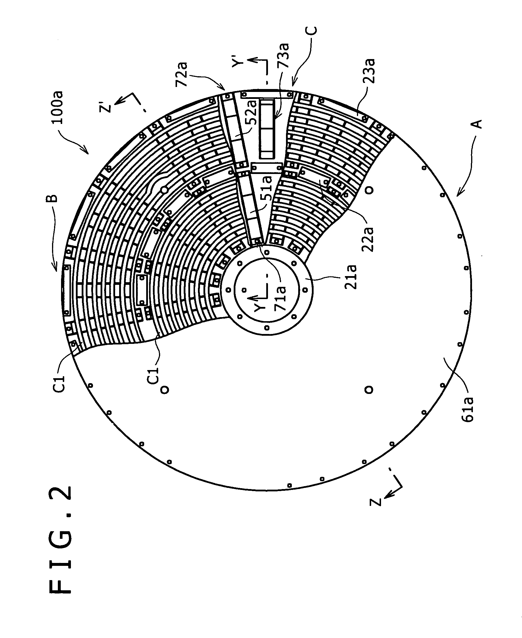
[0079](5) Ferromagnetic nonconductive members 51a, 52a: not used

[0080]The power factor (effectively used power / input power) was calculated by changing the distance L between the induction heating coil C1 and the nonmagnetic conductor 30a by adjusting the first spacers 71a and 72a (and third spacer 73a) while supplying power to the heating unit under the above condition. The test results are as follows (...

example 2

[0081]Results of heating test for the heating unit 100a with or without ferromagnetic nonconductive members 51a and 52a are shown. The condition thereof was set as follows.

(1) Power source: Rated 5 kw (set to maximum output)

(2) Nonmagnetic conductor 30a: aluminum (4 mm in thickness)

(3) Induction heating coil C1: 30 sq Teflon (trademark)-covered litz wire

(4) Distance between induction heating coil C1 and Ferromagnetic metallic member 10a: 21.5 mm (fixed)

(5) Distance between nonmagnetic conductor 30a and induction heating coil C1: 13 mm (fixed)

[0082]The test results in the above-mentioned conditions with or without the ferromagnetic nonconductive members 51a and 52a are as follows.

(1) Without ferromagnetic nonconductive members 51a and 52a, Power factor: 15.0%

(2) With ferromagnetic nonconductive members 51a and 52a, Power factor: 33.7%

The power factor in the heating unit 100a with the ferromagnetic nonconductive members 51a and 52a was high with an increased equivalent resistance, com...


PUM

PropertyMeasurementUnit
Magnetic fieldaaaaaaaaaa
Sizeaaaaaaaaaa
Distanceaaaaaaaaaa

Abstract

The present invention provides a heating unit capable of easily and inexpensively adjusting total impedance based on tire mold size so that a power source can be used at a high power factor, and a tire heating apparatus using the same. A ferromagnetic metallic member 10a heats a tire mold M1 by heat conduction. An induction heating coil C1 is disposed on the side of the ferromagnetic metallic member 10a opposite the tire mold M1 to induction-heat the ferromagnetic metallic member 10a by generating magnetic field lines. A nonmagnetic conductor 30a is disposed on the side of the induction heating coil C1 opposite the ferromagnetic metallic member 10a to shield the magnetic field lines generated by the induction heating coil C1. A heating unit 100a including these elements heats the tire mold M1 storing a tire. A relative positional relationship among the nonmagnetic conductor 30a, the induction heating coil C1 and the ferromagnetic metallic member 10a is set by first spacers 71a and 72a and second spacers 21a to 23a.

Description

FIELD OF THE INVENTION[0001]The present invention relates to a heating unit for heating a tire mold, a tire heating apparatus using the same, and further a method for remodeling a tire mold.BACKGROUND OF THE INVENTION[0002]Vulcanization molding of a green tire involves heating of the green tire. This heating is carried out, for example, by generating steam in a main boiler, supplying the heat of the steam into a steam flow passage within a tire mold containing the green tire through a steam pipe disposed in contact with the tire mold to heat the tire mold, and further transferring the heat of the tire mold to the tire. However, the heating using steam is inferior in heat efficiency since the thermal energy of the steam is lost by radiation from the surface of the steam pipe extending from the main boiler to the tire mold. Therefore, a technique for minimizing the loss of thermal energy is disclosed in Patent Reference 1, in which a metallic ring member contacting with a tire mold is...

Claims


Application Information

Patent Timeline
IPC IPC(8): H05B6/10
CPCB29C33/06B29C35/0805B29C2035/0811B29C2035/0816B29L2030/00B29D30/0605B29D2030/0674B29D2030/0677B29D30/0601B29D2030/0667Y02P70/10B29C33/02B29C35/02B29K2021/00B29K2105/24
Inventor OKADA, KAZUTOKUWABARA, HIDEAKIMITAMURA, HISASHIMURATA, TOMOMICHITOSHIMA, MASATAKEFUJIEDA, YASUHIKO
Owner KOBE STEEL LTD
Why Eureka
Try Eureka