Gamma-ray detector

a detector and gamma-ray technology, applied in the field of gamma-ray detection, can solve the problems of increasing the radiation exposure of the user seeking to identify, the detector is relatively heavy, and the overall complexity of the detector is increased, so as to reduce the optical crosstalk

Active Publication Date: 2009-12-17
SYMETRICA
View PDF10 Cites 29 Cited by
  • Summary
  • Abstract
  • Description
  • Claims
  • Application Information

AI Technical Summary

Benefits of technology

[0011]Thus a simple detector is provided that is able to determine the intensity, nature and direction of a source of gamma-rays using the same group of detection elements, namely the scintillation bodies. Accordingly, the detector does not require a separate direction finding component, and is thus able to include comparatively more scintillation material than would be possible in a detector of comparable characteristic size but including a direction finding components. Thus detectors according to embodiments of the invention are able to determine the direction to a source, while maintaining the sensitivity of similarly sized dedicated scintillator spectrometers
[0015]Thus a user can readily identify the intensity, nature and direction to a source of radiation so that he can quickly and fully assess the risk he is presented with.
[0016]Because the graphical indication comprises a plurality of geometric shapes having sizes determined according to the output signals from the photo-detectors, a user can intuitively assess which of the scintillation bodies is absorbing the greatest amount of radiation, and hence quickly determine to which side of the pointing axis the source is located.
[0017]The direction to a source within a given plane can be determined using only two scintillation bodies. Three scintillation bodies are enough to allow the direction to the source to be determined in three-dimensions. However, in some embodiments the gamma-ray detector consists of four scintillation bodies arranged in a two-by-two array about the pointing axis. This allows the direction to a source to be determined within three-dimensions using a simple configuration that makes efficient use of the volume available for the scintillation bodies.
[0018]The scintillation bodies in this arrangement may be square in cross-section in a plane perpendicular to the pointing axis of the detector since this allows them to be closely packed. A layer of optically opaque material, such as a metallic foil, may be provided between the scintillation bodies to reduce optical crosstalk between them.

Problems solved by technology

A problem with this approach is than it can be slow and unreliable, and so results in an increased radiation exposure to the user seeking to identify the source.
For example, the direction finding component 6 requires lead shielding and this makes the detector relatively heavy.
This can be a problem because the sensitivity of a scintillator-based spectrometer is closely tied to the volume of the scintillator material used.
Furthermore still, the inclusion of the separate direction finding component 6 adds to the overall complexity of the detector, for example because a separate high voltage supply and processing circuitry for the Geiger-Muller tubes are required.

Method used


Image

  • Gamma-ray detector
  • Gamma-ray detector
  • Gamma-ray detector

Examples


Embodiment Construction

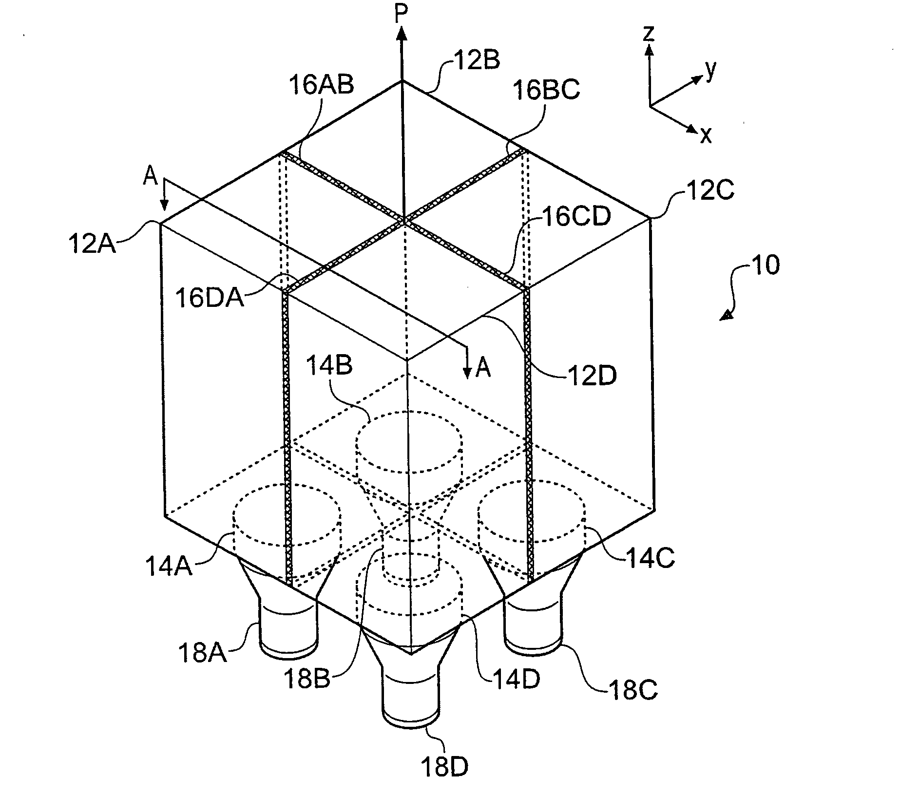
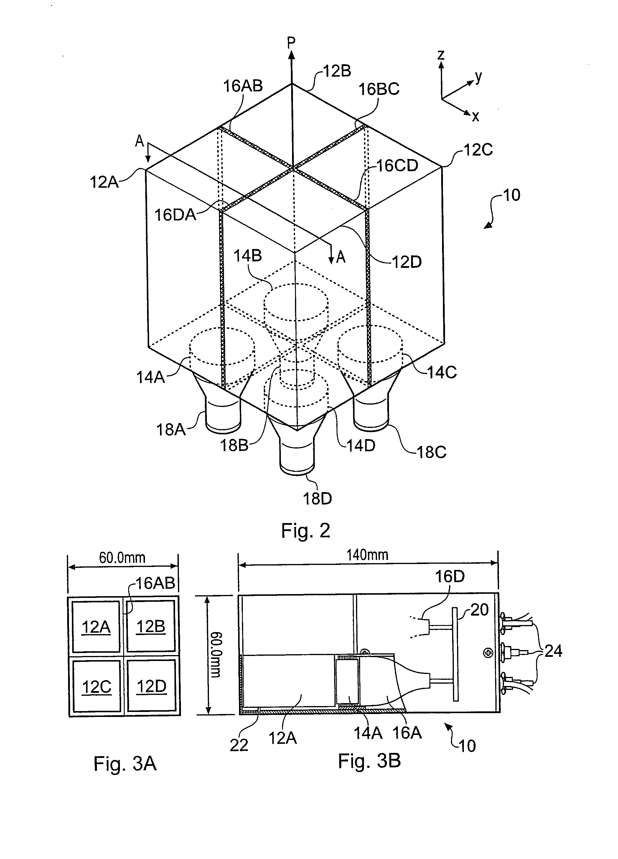
[0029]FIG. 2 schematically shows in perspective view a gamma-ray detector 10 for determining the direction to a gamma-ray source according to an embodiment of the invention. FIG. 3A schematically shows a plan view of the uppermost surface of the detector 10 shown in FIG. 2. FIG. 3B schematically shows a partial section view of the detector 10 taken along the section AA shown in FIG. 2. The orientation of a Cartesian coordinate system used to describe some aspects of the detector is shown to the top-right of FIG. 2.

[0030]The detector 10 comprises first, second, third and fourth Thallium-doped Sodium Iodide (NaI(Tl)) crystal scintillation bodies 12A-D. The four scintillation bodies are of generally square cross-section in the xy-plane and are arranged adjacent to one another in a two-by-two square array. Each scintillation body is separated from its two immediate neighbouring scintillation bodies by layers of aluminium foil. Thus, a first layer of aluminium foil 16AB is arranged betwe...


PUM


Abstract

A portable gamma-ray detector for indicating the intensity of a source of gamma-rays, the nature of the source, and the direction to the source relative to an axis of the detector. The detector comprises a plurality of scintillation bodies arranged around the pointing axis, for example four scintillation bodies in a two-by-two array and separated from each other by aluminium foil. Thus gamma-rays from different directions are shielded from different ones of the scintillation bodies by the other scintillation bodies. The scintillation bodies are coupled to respective photo-detectors and a processing circuit is configured to receive output signals from the photo-detectors and to provide an indication of the direction to a source relative to the pointing axis of the detector based on the relative output signals from the different photo-detectors. The processing circuit is further operable to determine the intensity of the source from the magnitudes of the output signals, and the nature of the source from a spectral analysis of the output signals.

Description

BACKGROUND ART[0001]The invention relates to gamma-ray detection, and in particular to gamma-ray detection for determining the direction to a source of gamma-rays.[0002]There are a number of situations in which it can be important to be able to quickly determine the level of radiation in the environment, the nature of the isotope producing the radiation, and the direction from which the radiation is coming. For example, this information can be of great benefit to emergency staff entering a ‘disorganised’ nuclear environment, for screening personnel and cargo in order to police the illicit trafficking of radioactive materials, and for general searching for ‘orphaned’ sources of radiation.[0003]Gamma-ray detectors with the ability to measure the intensity of radiation in the environment and to identify the nature of the source emitting the radiation (from spectroscopic information) are widely available, for example the GR-135 Exploranium® from the SAIC Corporation. However, to determi...

Claims


Application Information

Patent Timeline
Patent Type & Authority Applications(United States)
IPC IPC(8): G01T1/29
CPCG01T1/1644G01T7/00G01T1/2907
Inventor RAMSDEN, DAVIDBURT, CHRISTOPHER DAVID HENRY
Owner SYMETRICA
Why Eureka
Try Eureka