
Traveling working machine

Active Publication Date: 2009-12-17
LEIBHERR HYDRAULIKBAGGER GMBH
View PDF7 Cites 13 Cited by
  • Summary
  • Abstract
  • Description
  • Claims
  • Application Information

AI Technical Summary

Benefits of technology

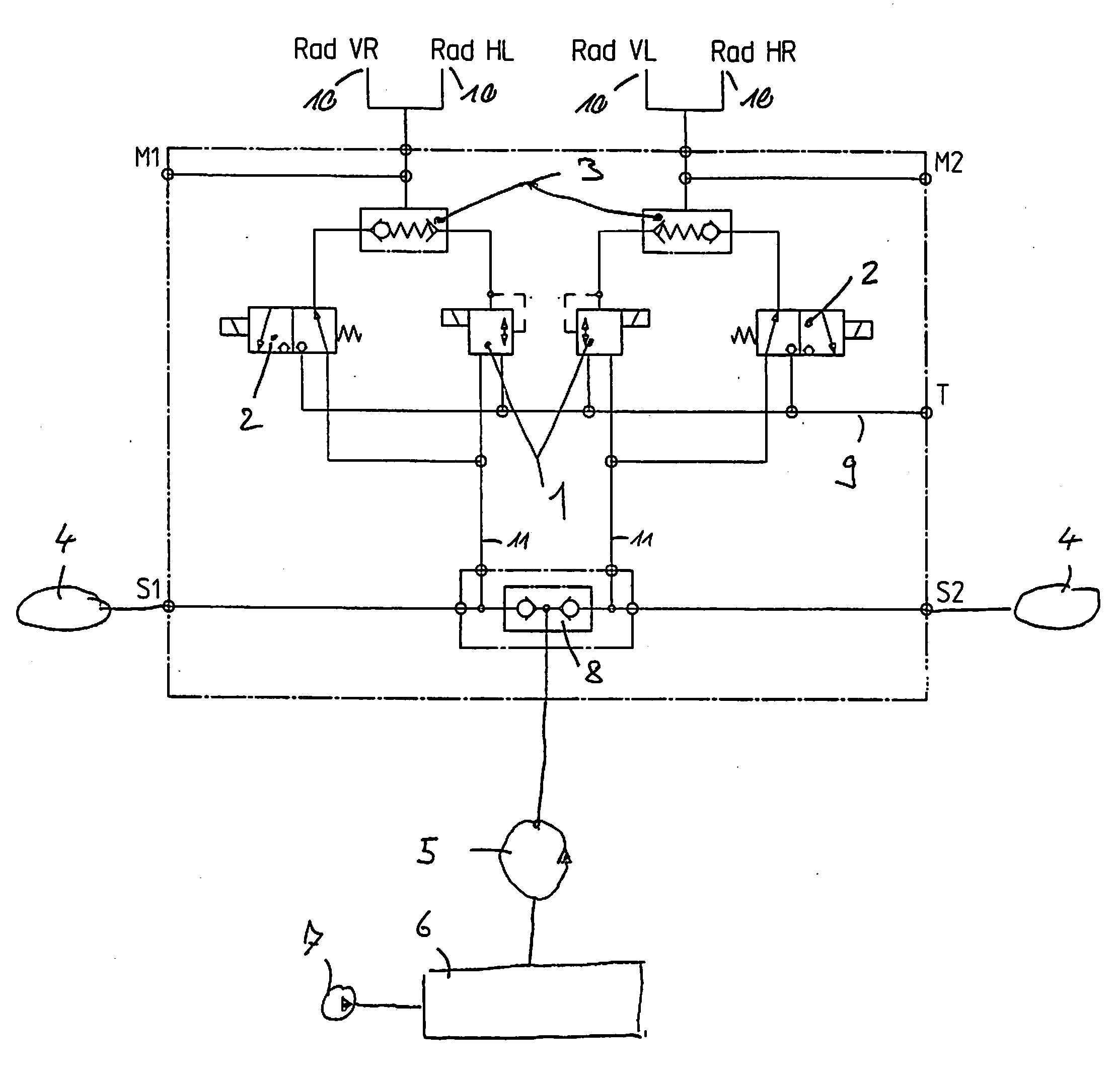
[0004]This object is solved by a traveling working machine according to the description herein. Such traveling working machine, in particular a hydraulic excavator, includes a traveling gear and a hydraulic service brake system for the traveling gear, which is supplied with brake pressure via at least one brake valve. In accordance with the invention, it is provided that the brake valve can be actuated electrically, wherein it is connected with a control element via an electric control line, by means of which an operator can brake the traveling working machine. Due to the electric actuation of the brake valve, the same can be arranged in direct vicinity of the brakes of the service brake system. As a result, disturbing hydraulic lines can be omitted in the operator cabin. The expensive tubing from the cabin to the traveling gear and back can also be omitted. The braking deceleration occurring in the case of long brake lines also can be avoided thereby.
[0006]Advantageously, the present invention is used in a traveling working machine with an undercarriage and an uppercarriage rotatably arranged thereon. Advantageously, the traveling working machine of the present invention therefore includes an undercarriage, on which the traveling gear, the service brake system and the brake valve are arranged, and an uppercarriage rotatably arranged on the undercarriage, on which the control element is arranged. In particular, the control element is disposed in the operator cabin arranged on the uppercarriage. Due to the fact that the actuation of the brake valve now is effected electrically, the number of rotary joint passages between the uppercarriage and the undercarriage can be reduced, so that the complexity of the rotary joint is decreased.
[0007]In a furthermore advantageous way, at least one hydraulic accumulator is provided, which supplies the hydraulic service brake system with pressure, wherein the accumulator is arranged in the undercarriage. This in turn results in short hydraulic paths and a compact arrangement of the hydraulic service brake system.
[0010]In a furthermore advantageous way, at least one reversing valve is provided, which in a case of emergency separates the brake valve from the service brake system and connects the emergency valve with the service brake system. In this way, it is ensured that in a case of emergency no pressure drop is obtained over a brake valve which e.g. is not completely closed.
[0014]In a furthermore advantageous way, the traveling working machine of the present invention includes at least two brake circuits, which separately are supplied with pressure via at least one brake valve each. By means of this redundant configuration, a double safety of the service brake system is obtained.
[0015]Advantageously, the two brake circuits are supplied with pressure via hydraulic accumulators, which are arranged in the undercarriage and which are charged via a common hydraulic line. Thus, there are provided two separate brake circuits with their respective hydraulic accumulators, wherein nevertheless only one rotary joint passage is necessary for charging the same. In turn, this provides a particularly simple construction.

Problems solved by technology

Especially in a cabin with a hoisting gear or a glass bottom in the cabin, such hydraulic lines are extremely disturbing.
In addition, large machines involve the problem that a braking deceleration occurs due to the very long brake lines from the cabin to the traveling gear.

Method used


Image

  • Traveling working machine
  • Traveling working machine

Examples


Embodiment Construction

[0017]The only FIGURE shows a first embodiment of a service brake system of a traveling working machine in accordance with the invention.

[0018]The traveling working machine advantageously is a construction machine, in particular a construction machine with a hydraulic drive for the traveling gear and / or the working machines, in particular a hydraulic excavator.

[0019]In the embodiment of a service brake system as shown in the only FIGURE, the hydraulic service brake system for the traveling gear includes brakes 10, by means of which the wheels of the traveling gear can be braked while driving. The service brake system with the brakes 10 is supplied with pressure via the brake valves 1, wherein the brake valves 1 can be actuated electrically in accordance with the invention. There is provided an electric control line, via which the brake valves 1 are connected with a control element, by means of which an operator can brake the traveling working machine.

[0020]Due to the electronic actu...


PUM


Abstract

The present invention relates to a traveling working machine, in particular a hydraulic excavator, with a traveling gear and with a hydraulic service brake system for the traveling gear, which is supplied with brake pressure via at least one brake valve. In accordance with the invention, the brake valve can be actuated electrically, wherein it is connected with a control element via an electric control line, by means of which an operator can brake the traveling working machine.

Description

BACKGROUND OF THE INVENTION[0001]The present invention relates to a traveling working machine, in particular a hydraulic excavator, with a traveling gear and with a hydraulic service brake system for the traveling gear, which is supplied with brake pressure via at least one brake valve. Via this hydraulic service brake system, the traveling working machine can be braked while driving. In particular, the present invention relates to traveling construction machines with a corresponding service brake system.[0002]In known traveling working machines with a hydraulic service brake system, the brake valves via which the brake pressure is controlled are arranged in the operator cabin and can be actuated mechanically by the operator via a control element, e.g. a brake pedal. As a result, long hydraulic lines from the brake valve to the brakes must be provided for the traveling gear. Especially in a cabin with a hoisting gear or a glass bottom in the cabin, such hydraulic lines are extremely...

Claims


Application Information

Patent Timeline
IPC IPC(8): B60T13/74
CPCB60T10/04B60T13/686E02F9/226E02F9/2228E02F9/2217
Inventor MEIER, SIMON
Owner LEIBHERR HYDRAULIKBAGGER GMBH
Learn More