Motor drive system

Active Publication Date: 2014-01-02
ICHINOMIYA ELECTRIC
View PDF3 Cites 10 Cited by
  • Summary
  • Abstract
  • Description
  • Claims
  • Application Information

AI Technical Summary

Benefits of technology

The present invention provides a three-phase brushless motor that satisfies the design concept of double safety and can suppress a reduction in output and cost increase. The motor has multiple coils that produce induced voltage in the same phase. This results in a synergized voltage that maximizes the output of the motor. The motor and its drive system achieve double safety and prevent a decline in motor performance or increase in cost.

Problems solved by technology

However, providing the two sets doubles the cost and the space, and therefore such a structure is not realistic.
As a result, a problem such that the output of the motor decreases occurs.

Method used


Image

  • Motor drive system
  • Motor drive system
  • Motor drive system

Examples


embodiment 1

Schematic Configuration of Brushless Motor 10

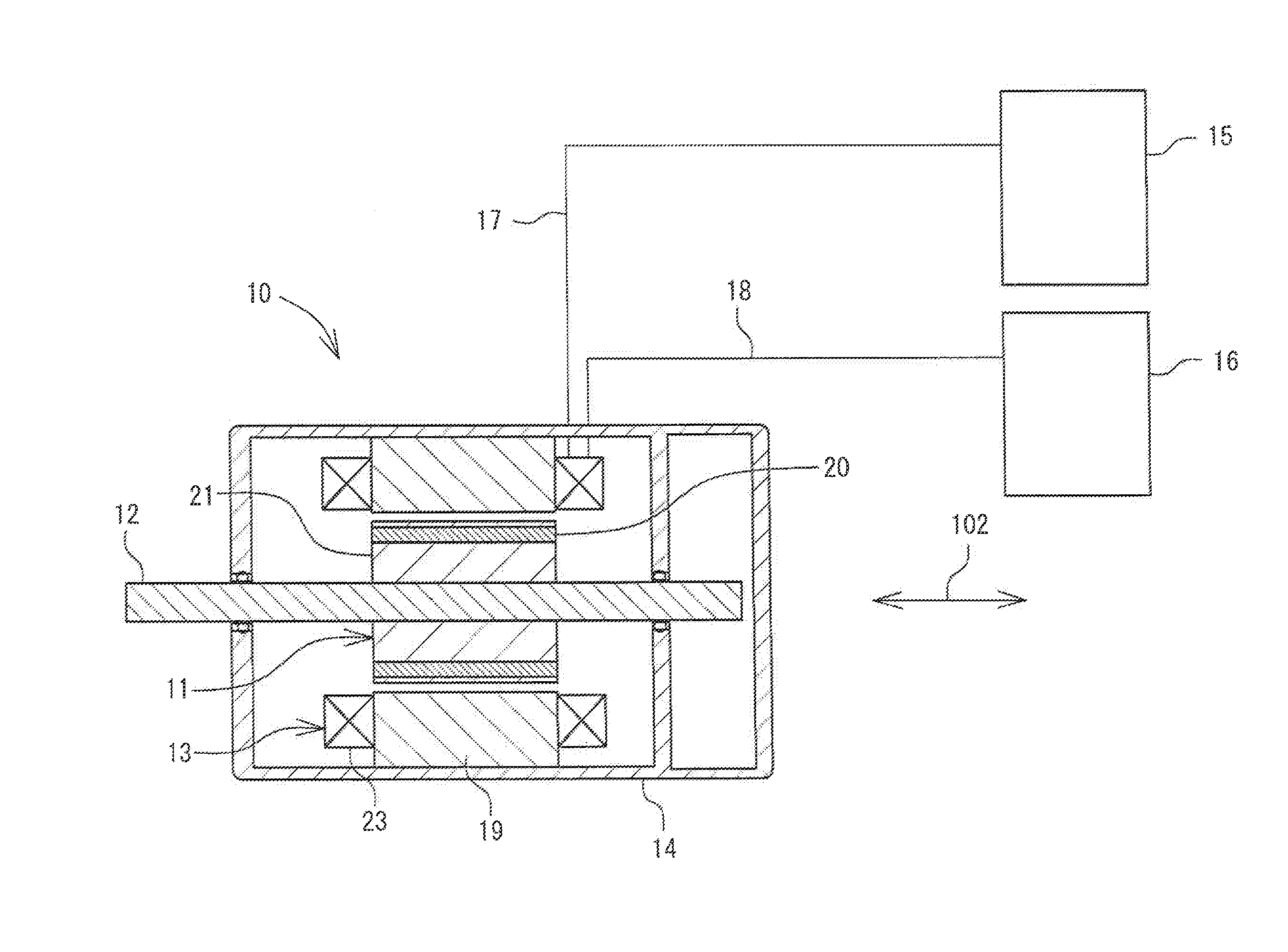
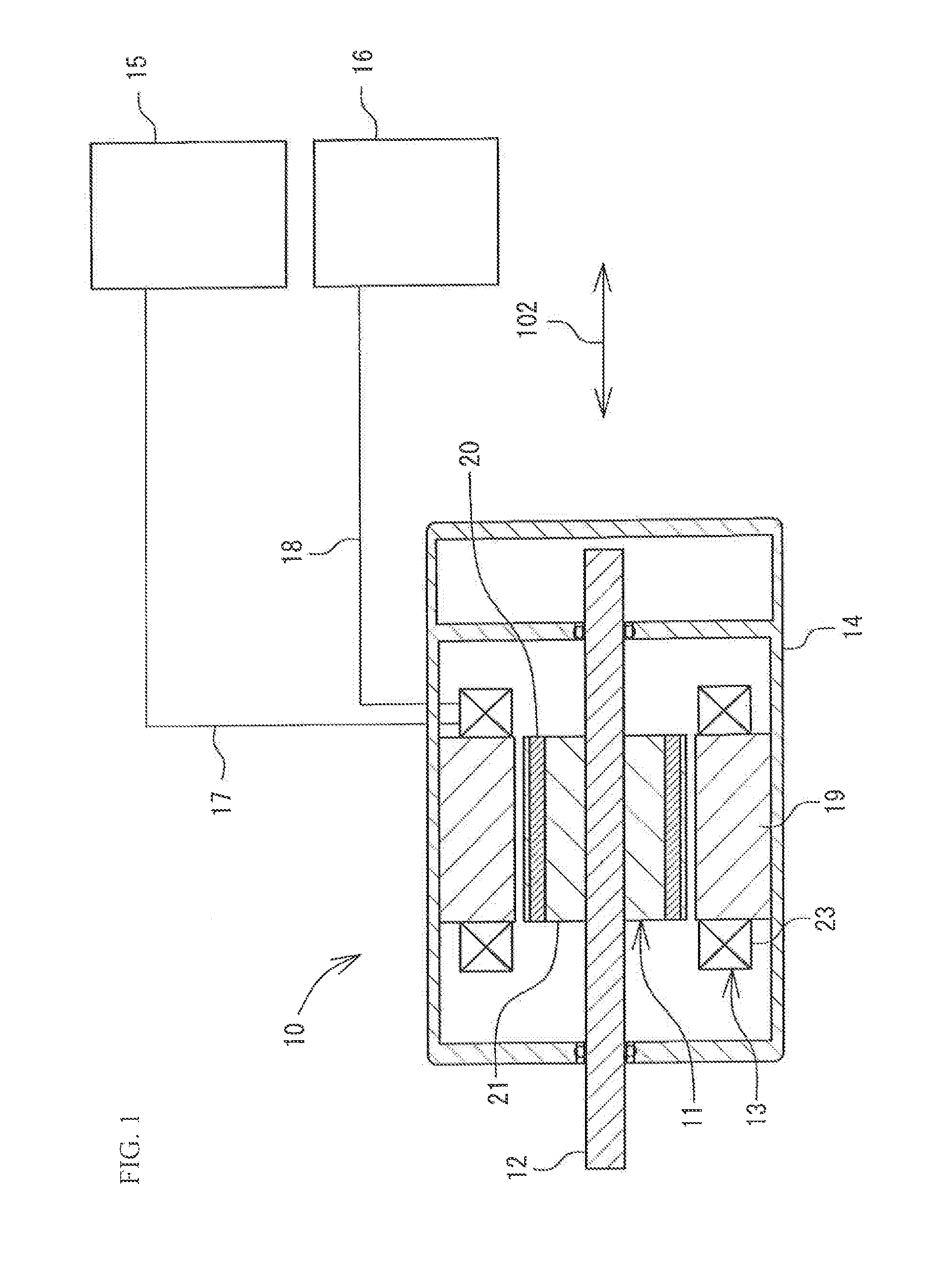
[0032]A brushless motor 10 illustrated in FIG. 1 has a rotor 11, a shaft 12, a stator 13, a housing 14, and the like. The housing 14 houses the rotor 11, the shaft 12, and the stator 13 therein. The brushless motor 10 is electrically connected to two controllers 15 and 16 which supply electric power by harnesses 17 and 18. Each of the controllers 15 and 16 is electrically connected to coils 23 of the stator 13. The electric power supplied from each of the controllers 15 and 16 is applied to each coil 23. Each of the controllers 15 and 16 supplies three-phase voltages of a U phase, a V phase, and a W phase. A motor drive system according to Embodiment 1 is constituted by the brushless motor 10 and the controllers 15 and 16.

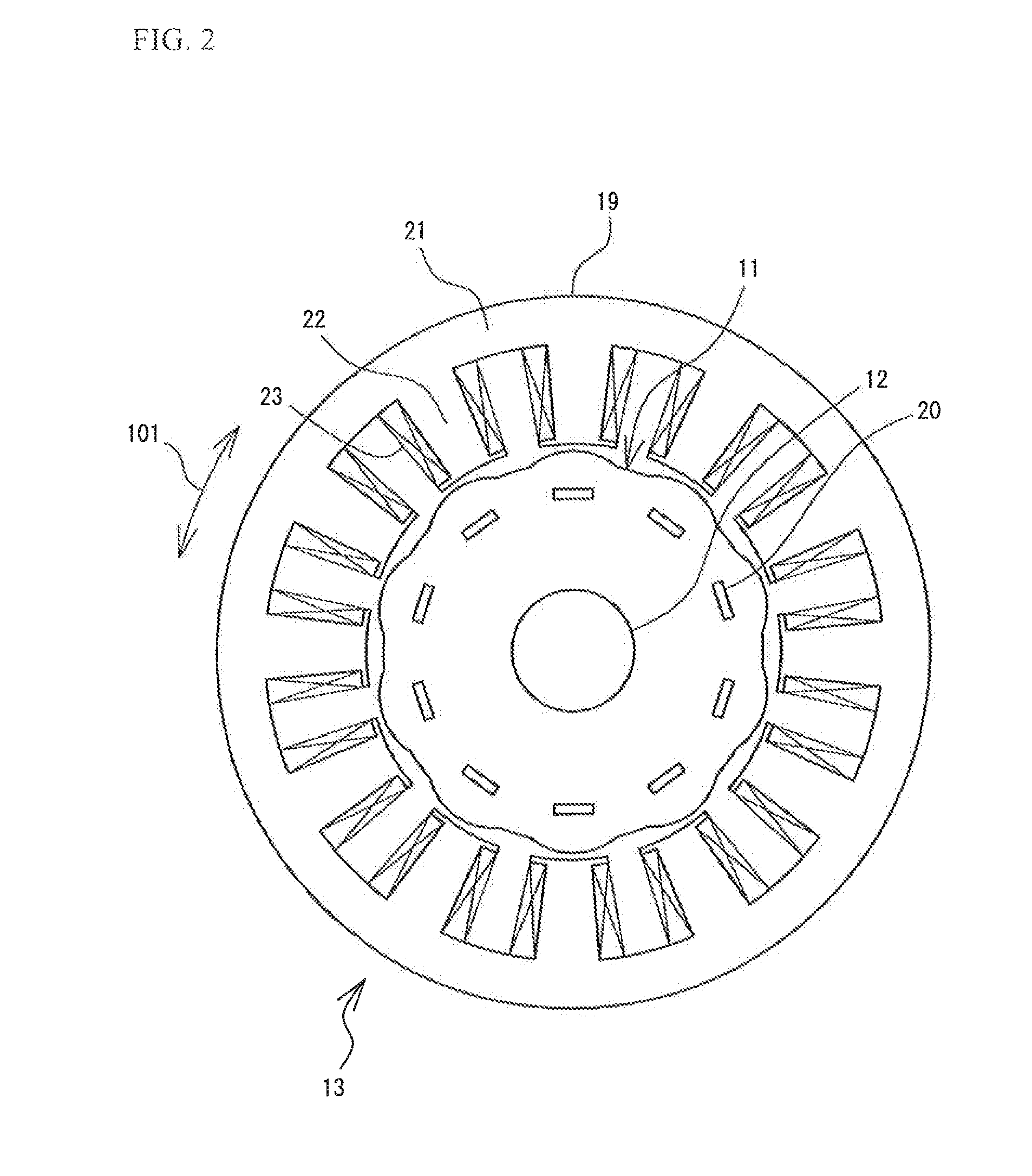
[0033]As illustrated in FIGS. 1 and 2, the rotor 11 has an approximately cylindrical shape and is provided with ten magnets 20 which are equally separated along a circumferential direction 101. In the rotor 11, a plurali...

embodiment 2

[0055]Next, a motor drive system according to Embodiment 2 of the invention is described with reference to FIGS. 9 and 10. Since a fundamental configuration is common to that of FIG. 1, the constituent components common to those of FIG. 1 are designated by the same reference numerals, a detailed description thereof is omitted, and the description is given focusing on differences.

[0056]As illustrated in FIG. 9, the motor drive system according to Embodiment 2 is different from that of Embodiment 1 in that the brushless motor 10 further has a first resolver 31 (first sensor) and a second resolver 32 (second sensor). The first resolver 31 and the second resolver 32 are sensors which output electric signals according to the rotation angle of a shaft 12 (rotor shaft). A sensor portion according to Embodiment 2 is constituted by the two sensors.

[0057]As illustrated in FIG. 10, the first resolver 31 has a resolver rotor 49 and a resolver stator 48 having resolver teeth 44, a stator body 45...


PUM


Abstract

A motor drive system has a brushless motor having coils classified into a group A and a group B, a stator having 12 teeth, around each of which any one of the coils classified into the group A and the group B is wound, and a shaft and a rotor which are provided inside the stator; a controller which applies three-phase voltages to each coil of the group A; a controller which applies the three-phase voltages to each coil of the group B; and a sensor portion which outputs an electric signal according to the rotation angle of the shaft to the controllers. Both the total number of the coils of the group A and the total number of the coils of the group B are 6.

Description

TECHNICAL FIELD[0001]The present invention relates to a three-phase brushless motor to which two electrically independent controllers are connected and a motor drive system.BACKGROUND OF THE INVENTION[0002]For example, in vehicles, a brushless motor is used as a drive source for assisting the rotation of a steering and the like. Moreover, the brushless motor is used also as a drive source which rotates a steering when detecting the lane of a road and a vehicle running immediately ahead, and then automatically operating a vehicle based on a signal of the detection.[0003]As described above, the brushless motor used as the drive source which rotates a steering has been required to have high reliability. Furthermore, the brushless motor has been required to be designed in such a manner as to perform a minimum function even when a failure, such as disconnection, occurs in coils constituting the brushless motor. For example, Patent Literature 1 discloses a configuration such that a switch...

Claims


Application Information

Patent Timeline
IPC IPC(8): H02P25/22H02P6/06H02P6/08H02P27/06H02P27/08
CPCH02P25/22H02K3/28H02K16/04H02K11/225
Inventor KINASHI, YOSHIKAZU
Owner ICHINOMIYA ELECTRIC
Why Eureka
Try Eureka