
High torque density electrical machine

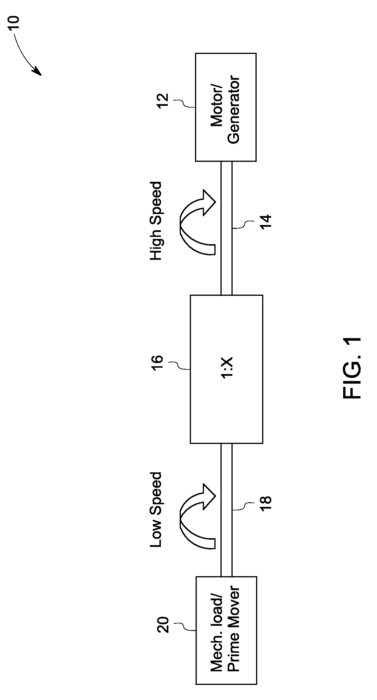
a high torque density, electrical machine technology, applied in the direction of mechanical energy handling, magnetic circuit rotating parts, magnetic circuit shape/form/construction, etc., can solve the problems of high torque and power, electrical machines that deliver higher torque at lower speeds are expensive, and the need for continuous lubrication and maintenance of such mechanical equipmen

Inactive Publication Date: 2009-12-17
GENERAL ELECTRIC CO
View PDF7 Cites 28 Cited by
  • Summary
  • Abstract
  • Description
  • Claims
  • Application Information

AI Technical Summary

Problems solved by technology

However, certain applications require high torque and power at low speeds.
Generally, electrical machines that deliver higher torque at lower speeds are expensive.
However, certain undesirable factors such as additional cost, acoustic noise, and mechanical wear and tear lead to a need for continuous lubrication and maintenance of such mechanical equipment.
However magnetic gearing is of a relatively complex design, and provides relatively low torque density.
However, such systems require additional stationary windings resulting in a complex construction.

Method used


Image

  • High torque density electrical machine
  • High torque density electrical machine
  • High torque density electrical machine

Examples


Embodiment Construction

[0028]In accordance with embodiments of the present invention, systems and methods for high torque density electrical machines are described herein. In the following detailed description, numerous specific details are set forth in order to provide a thorough understanding of various embodiments of the present invention. However, those skilled in the art will understand that embodiments of the present invention may be practiced without these specific details, that the present invention is not limited to the depicted embodiments, and that the present invention may be practiced in a variety of alternative embodiments. In other instances, well known methods, procedures, and components have not been described in detail.

[0029]Furthermore, various operations may be described as multiple discrete steps performed in a manner that is helpful for understanding embodiments of the present invention. However, the order of description should not be construed as to imply that these operations need ...


PUM


Abstract

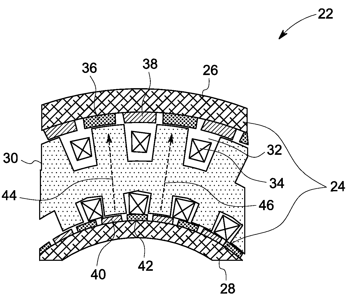
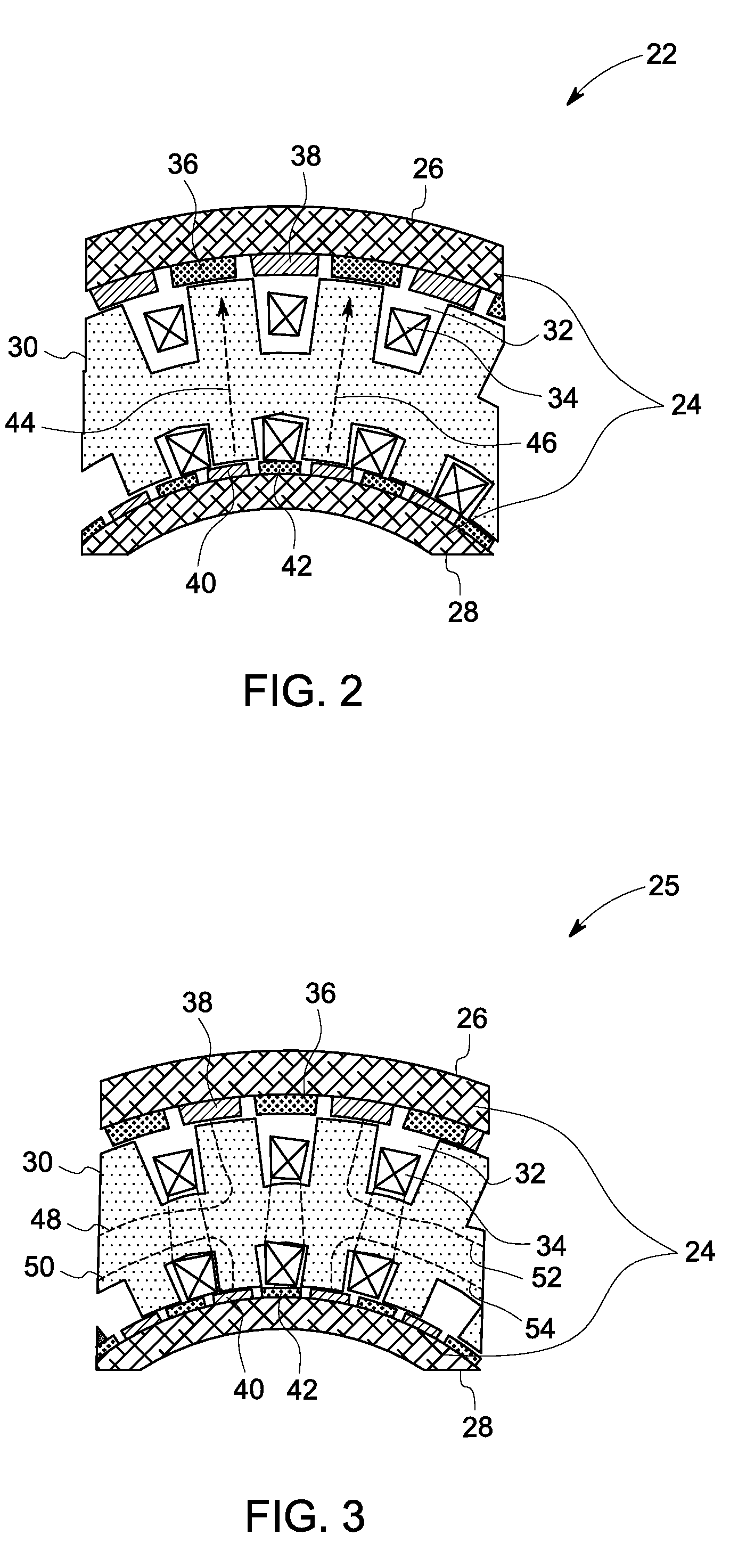
An electrical machine is provided. The electrical machine includes a rotor comprising an inner rotor having a plurality of inner rotor poles and an outer rotor having a plurality of outer rotor poles. The electrical machine further comprises a stator configured to modulate a magnetic flux and to transmit torque to inner rotor and the outer rotor, the stator comprising a stator core interposed concentrically between the inner rotor and the outer rotor; a multiple of stator windings disposed in a plurality of stator slots, the stator windings configured to form a multiple of stator poles. The stator further comprises a plurality of stator teeth interposed between the plurality of stator slots, wherein an arithmetic sum or difference of twice number of stator teeth and a number of the stator poles equals a number of rotor poles.

Description

BACKGROUND[0001]The invention relates generally to electrical machines and in particular, to high torque density electrical machines.[0002]Electrical machines, such as motors and generators are typically capable of delivering high torque and power at high speeds. However, certain applications require high torque and power at low speeds. Generally, electrical machines that deliver higher torque at lower speeds are expensive. Alternatively, a high torque at low speeds may be achieved by incorporating mechanical gearing for speed reduction. However, certain undesirable factors such as additional cost, acoustic noise, and mechanical wear and tear lead to a need for continuous lubrication and maintenance of such mechanical equipment.[0003]Magnetic gears offer significant benefits as compared to their mechanical counterparts. These benefits include accurate position control on a drive shaft, higher torque at very low speed, and a lack of physical contact between an input shaft and an outp...

Claims


Application Information

Patent Timeline
IPC IPC(8): H02K16/02H02K16/04H02K1/12H02K1/22
CPCH02K7/1823H02K16/02H02K21/02H02K21/12H02K16/04H02K1/145H02K1/276H02K1/2773H02K1/2793H02K21/24H02K1/2798
Inventor QU, RONGHAIJANSEN, PATRICK LEE
Owner GENERAL ELECTRIC CO
Features
  • Generate Ideas
  • Intellectual Property
  • Life Sciences
  • Materials
  • Tech Scout
  • Unparalleled Data Quality
  • Higher Quality Content
  • 60% Fewer Hallucinations
Learn More