
Backlight assembly and display apparatus having the same

Inactive Publication Date: 2009-12-17
SAMSUNG DISPLAY CO LTD
View PDF7 Cites 26 Cited by
  • Summary
  • Abstract
  • Description
  • Claims
  • Application Information

AI Technical Summary

Benefits of technology

[0008]Embodiments of the disclosure provide a backlight assembly having optimized connections and electrical stability.
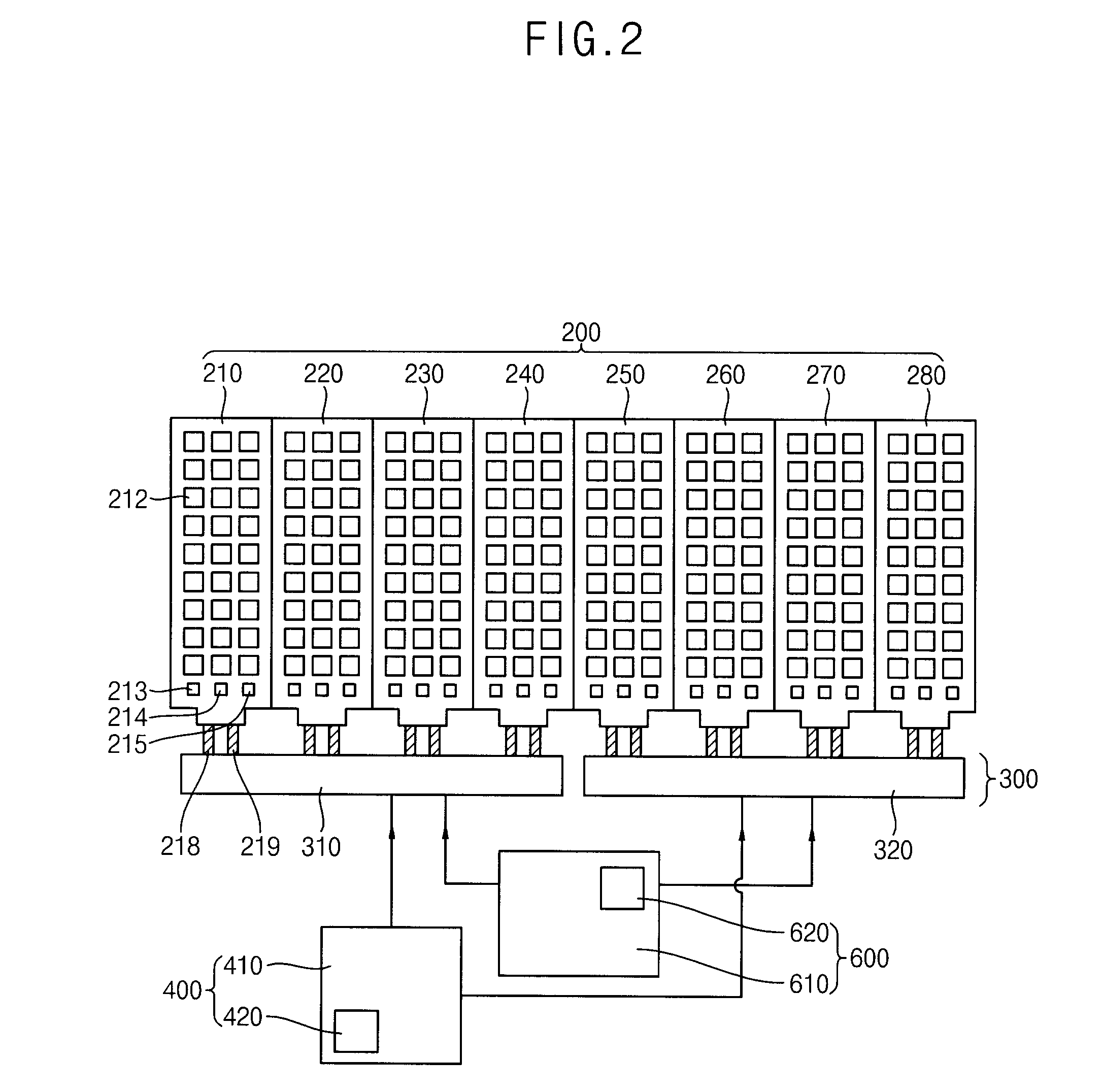
[0015]According to the embodiments of the disclosure, a control circuit board and a main circuit board are connected by a sub-circuit board, and the sub-circuit board amplifies a control signal received from the control circuit board and outputs the control signal to the main circuit board. Thus, the number of signal lines in the control circuit board, which is electrically connected to the main circuit board, may be decreased and loads in the control circuit board may be decreased, and thus the control circuit board may be electrically stable.

Problems solved by technology

As the number of signal lines increases, electrically connecting the signal lines of the light-driving board and those of the light-generating board may be difficult.
Moreover, signal line connections may be prone to disconnection, or a large number of signal lines may have a disorderly appearance.

Method used


Image

  • Backlight assembly and display apparatus having the same
  • Backlight assembly and display apparatus having the same
  • Backlight assembly and display apparatus having the same

Examples


embodiment 1

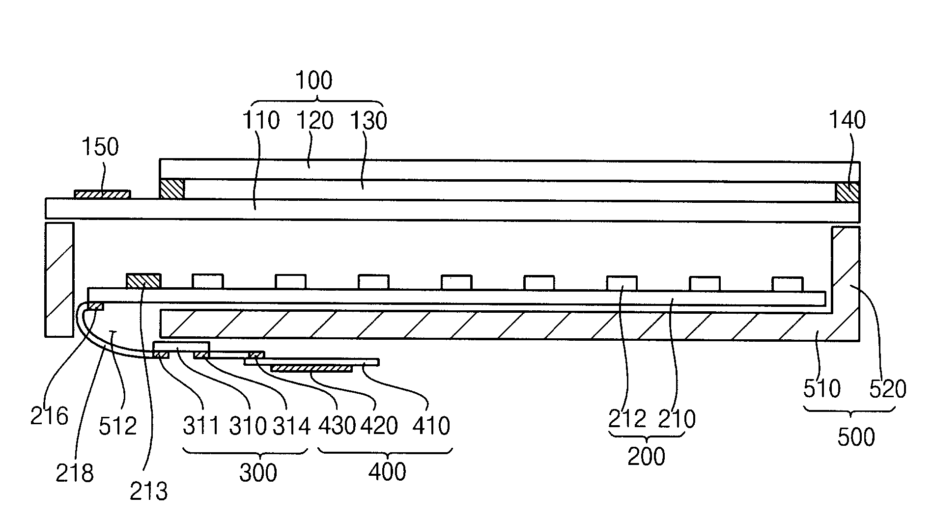
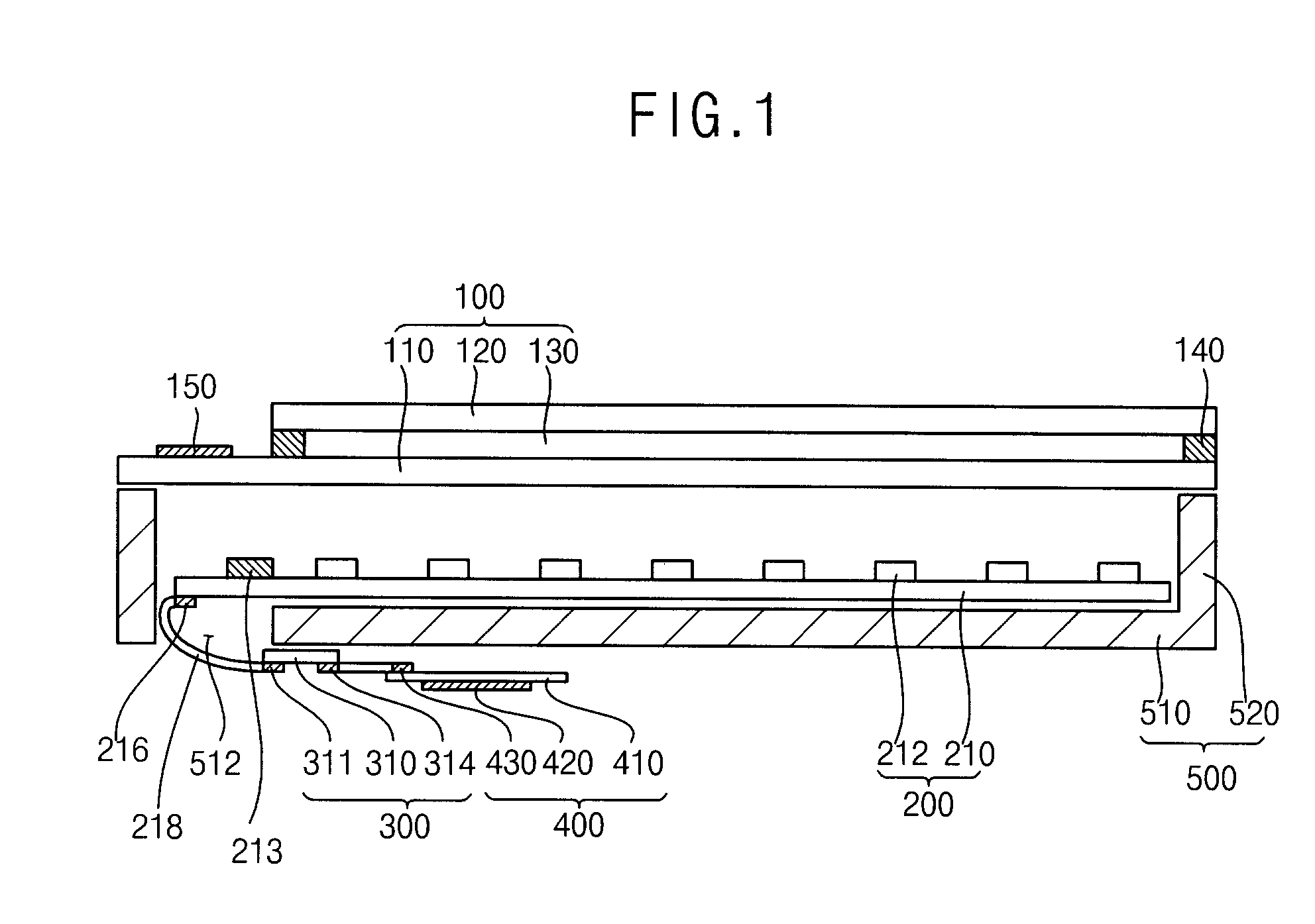
[0033]FIG. 1 is a cross-sectional view showing an exemplary embodiment of a display apparatus in accordance with

[0034]FIG. 2 is a plan view showing an exemplary embodiment of a backlight assembly shown in FIG. 1, and FIG. 3 is a rear view showing an exemplary embodiment of the backlight assembly shown in FIG. 2.

[0035]Referring to FIGS. 1, 2 and 3, a display apparatus in accordance with Embodiment 1 includes a display panel 100 which displays an image using light and a backlight assembly.

[0036]The display panel 100 may display an image using the light provided from the backlight assembly. The display panel 100 includes a first substrate 110, a second substrate 120, and a liquid crystal layer 130. The first substrate 110 may include a panel driving chip which drives the display panel 100. The first substrate 110 and the second substrate 120 may be adhered to each other by a sealant 140.

[0037]The first substrate 110 may include a gate line (not shown), a data line (not shown) crossing ...

embodiment 2

[0101]Hereinafter, a backlight assembly in accordance with Embodiment 2, and a display apparatus having the backlight assembly, will be described with reference to FIGS. 6 and 7.

[0102]FIG. 6 is a cross-sectional view illustrating an exemplary embodiment of a display apparatus in accordance with Embodiment 2, and FIG. 7 is a rear view showing an exemplary embodiment of the backlight assembly shown in FIG. 6.

[0103]In FIGS. 6 and 7, a backlight assembly and a display apparatus having the same, in accordance with Embodiment 2, is substantially the same as the backlight assembly in accordance with Embodiment 1, and the display apparatus having the backlight assembly previously described above, except for the arrangement of a plurality of main circuit boards, a first sub-circuit board, and a second sub-circuit board, and the structure of a bottom face in a container. Thus, any further description will be omitted.

[0104]Referring to FIGS. 6 and 7, in Embodiment 2 a first sub-circuit board 3...

embodiment 3

[0106]FIG. 8 is a schematic circuit view showing an exemplary embodiment of a buffer unit in accordance with

[0107]In FIG. 8, the schematic circuit view of a buffer unit in accordance with Embodiment 3 is substantially the same as the schematic circuit view in accordance with Embodiment 1, except for a select signal line. Thus, any further description will be omitted.

[0108]Referring to FIG. 8, a control circuit board 410 includes a select signal line 15. A control circuit part generates a chip select signal (CS), and the chip select signal (CS) is transmitted through the select signal line 15.

[0109]The select signal line 15 is connected to a main circuit board 210 and transmits the chip select signal (CS) to the main circuit board 210. The select signal line 15 is electrically connected to a first sub-circuit board 310 through a data input connector 313, and the select signal line 15 extending in the first sub-circuit board 310 is electrically connected to a buffer 316. The data inpu...


PUM


Abstract

A backlight assembly includes a main circuit board having a light-generating part, a control circuit board which provides a control signal for controlling the light-generating part, and a sub-circuit board which is electrically connected to the control circuit board and receives the control signal, the sub-circuit board including a buffer which generates an amplified control signal in response to the control signal, and where the sub-circuit board is electrically connected to the main circuit board and provides the amplified control signal. The control circuit board and the main circuit board are electrically connected by the sub-circuit board, and the sub-circuit board amplifies the control signal received from the control circuit board and provides the control signal to the main circuit board.

Description

[0001]This application claims priority to Korean Patent Application No. 2008-55768, filed on Jun. 13, 2008, and all the benefits accruing therefrom under 35 U.S.C. § 119, the contents of which in its entirety are herein incorporated by reference.BACKGROUND OF THE INVENTION[0002]1. Field of the Invention[0003]This disclosure relates to a backlight assembly and a display apparatus having the same.[0004]2. Description of the Related Art[0005]A liquid crystal display (“LCD”) apparatus includes an LCD panel which displays an image, a backlight assembly which provides light to the LCD panel, and a driving unit which drives the LCD panel.[0006]The backlight assembly may include a light source for generating light. Exemplary light sources include a cold cathode fluorescent lamp (“CCFL”), a hot cathode fluorescent lamp (“HCFL”), or a light-emitting diode (“LED”). LEDs are used commercially as a light source for LCDs because LEDs have low power consumption and high color reproducibility. A re...

Claims


Application Information

Patent Timeline
IPC IPC(8): H01K1/62
CPCG02F1/133603G02F2001/133601G02F2001/133612H05K1/148G09G2300/0426G09G2330/02H05K1/141G09G3/3406G02F1/133601G02F1/133612G02F1/1335G02F1/133
Inventor PARK, SANG-ILKIM, GI-CHERLPARK, SE-KISONG, SI-JOONCHANG, MOON-HWAN
Owner SAMSUNG DISPLAY CO LTD
Learn More