Induction heating cooker
- Summary
- Abstract
- Description
- Claims
- Application Information
AI Technical Summary
Benefits of technology
Problems solved by technology
Method used
Image
Examples
first embodiment
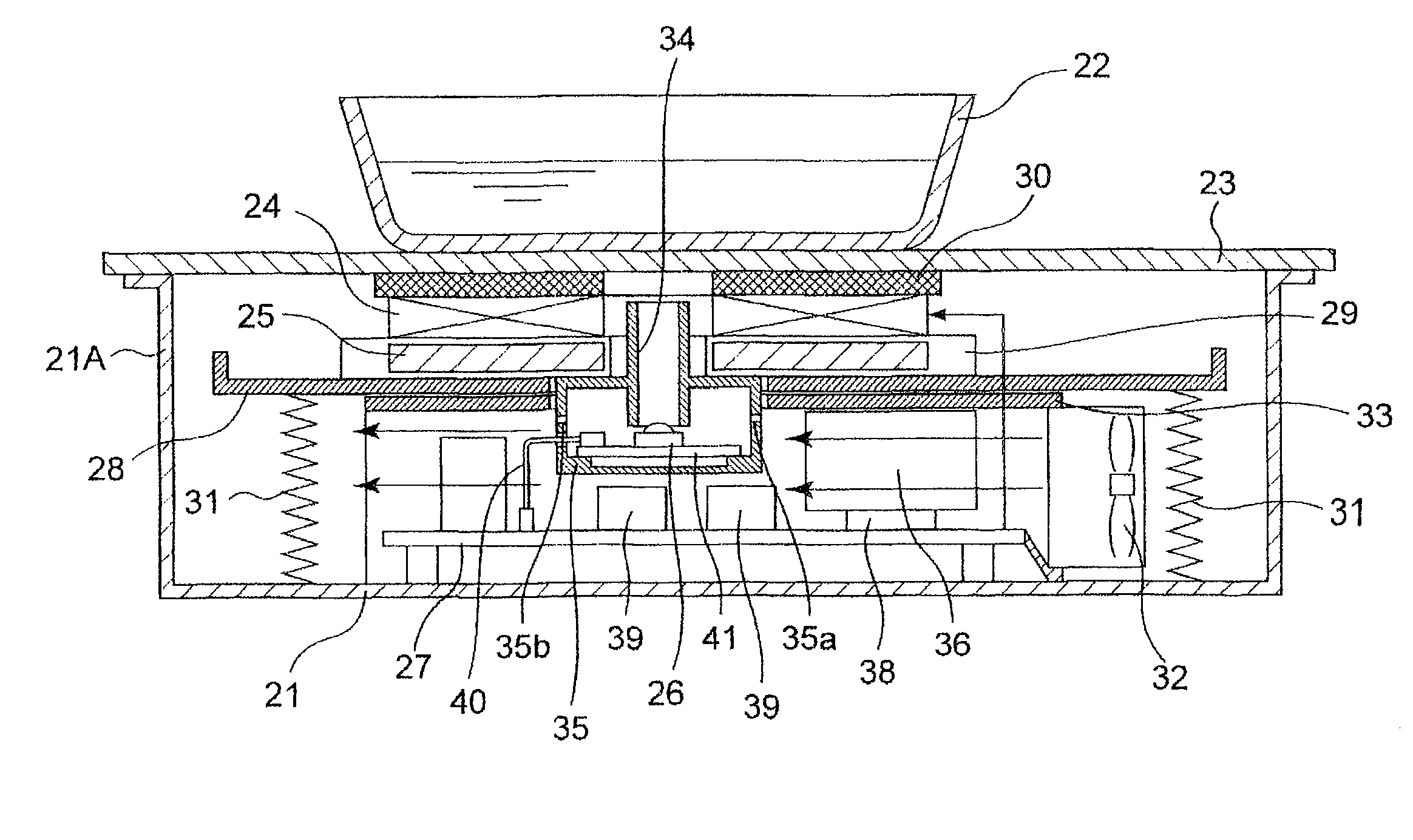
[0061]FIG. 1 is a cross-sectional view schematically showing the structure of an induction heating cooker according to a first embodiment of the present invention.
[0062]As shown in FIG. 1, the induction heating cooker according to the first embodiment has a box-like shape whose top portion is open, and includes a body 21 which structures an outer casing of the cooker. At the top portion of the body 21, a flat top plate 23 on which a cooking vessel 22 is placed is provided so as to cover the top portion opening of the body 21.
[0063]In the body 21 and below the top plate 23, a ring-like heating coil 24 that inductively heats the cooking vessel 22 is provided. Between the heating coil 24 and the top plate 23, in order to reduce the effect of the heat generated by the heated cooking vessel 22 on the heating coil 24, a heat insulating material 30 made of ceramic fibers or the like is provided.
[0064]Below the heating coil 24, ferrite elements 25 being one example of a plurality of magneti...
second embodiment
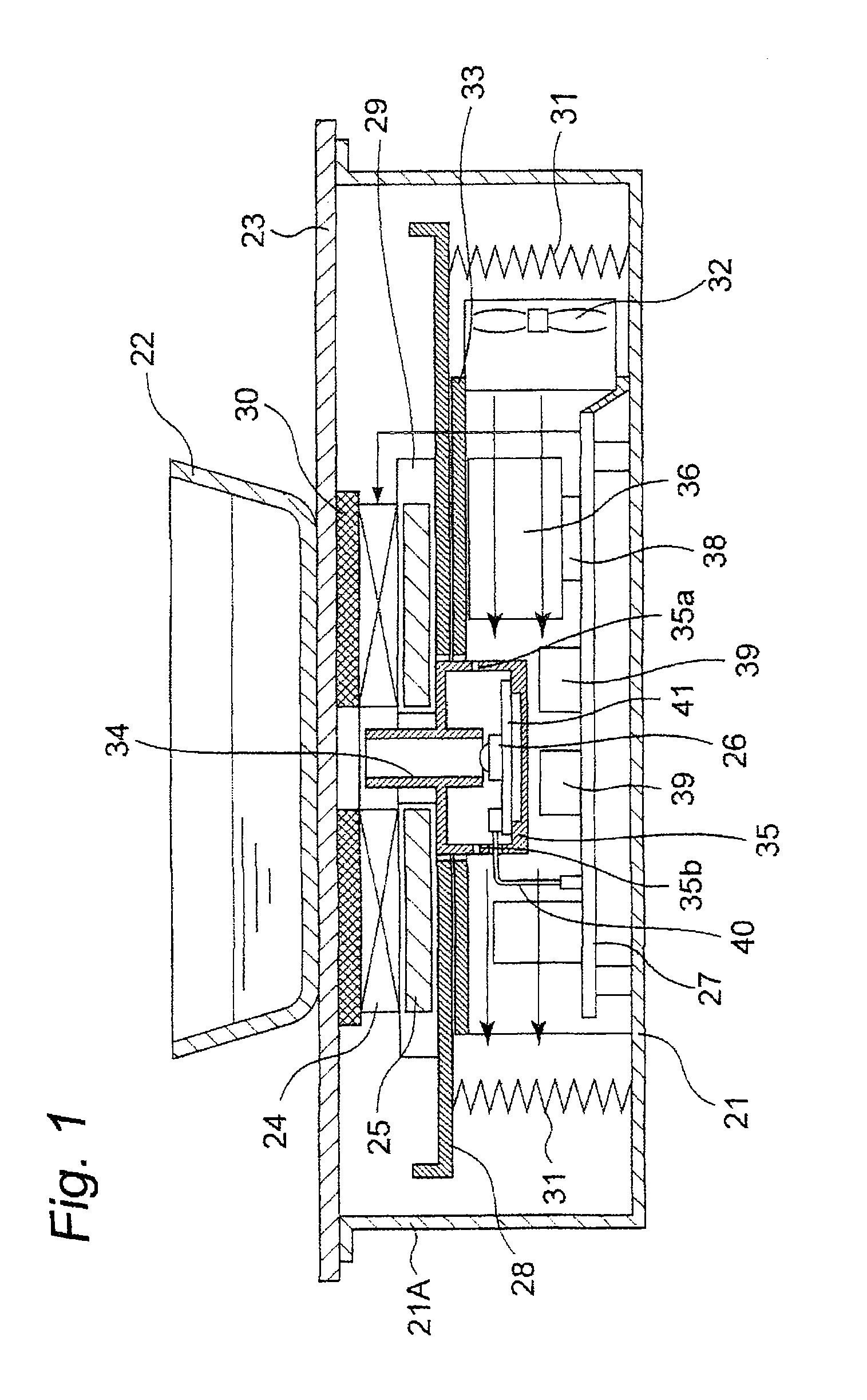
[0089]FIG. 2 is a cross-sectional view showing the structure of an induction heating cooker according to a second embodiment of the present invention. The induction heating cooker according to the second embodiment is different from the induction heating cooker according to the first embodiment in that the top surface of the casing 35 is attached to the bottom surface of the top wall of the duct 33, and the casing 35 and the duct 33 are integrally structured.
[0090]According to the second embodiment, since the casing 35 and the duct 33 are integrally structured, the layout of the wiring 40 can be set before the control circuit 27 is covered by the duct 33. Accordingly, the layout of the wiring 40 electrically connecting between the infrared sensor 26 and the control circuit 27 can further be simplified, and the assemblability can be improved.
[0091]Further, according to the second embodiment, the size of the hole provided to the heat dissipating plate 28 and the duct 33 so as to allow...
third embodiment
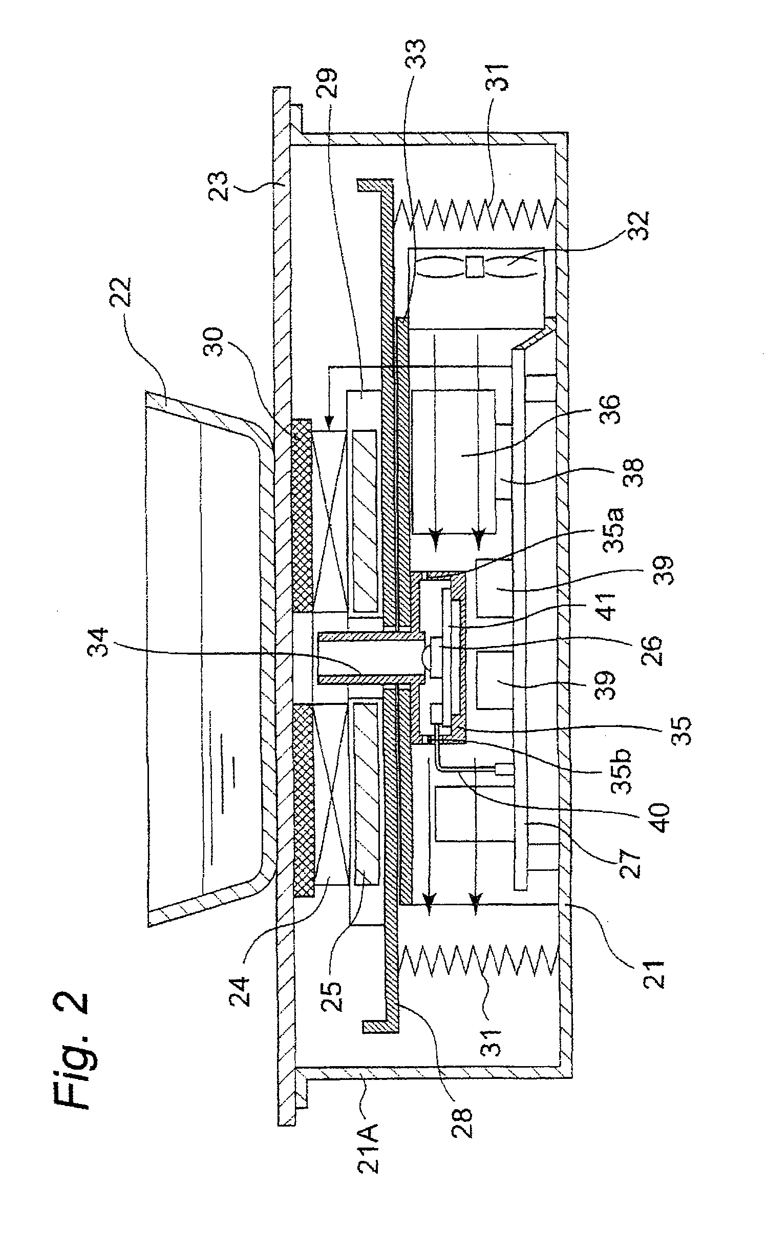
[0094]FIG. 3 is a cross-sectional view showing the structure of an induction heating cooker according to a third embodiment of the present invention. The induction heating cooker according to the third embodiment is different from the induction heating cooker according to the first embodiment in that the infrared sensor 26 and the control circuit 27 are mounted on the same circuit board, and a casing 35A is attached to the control circuit 27 so as to cover the infrared sensor 26.
[0095]According to the third embodiment, since the infrared sensor 26 is mounted on the circuit board identical to that on which the control circuit 27 is mounted, the electrical connection between the infrared sensor 26 and the control circuit 27 can be established by a pattern on the circuit board without dispensing with the wiring 40. Accordingly, the assemblability can further be improved.
[0096]It is noted that, in this case, by allowing the cooling air from the air blower 32 to blow in the wiring patter...
PUM
 Abstract
Description
Claims
Application Information
 - R&D
- Intellectual Property
- Life Sciences
- Materials
- Tech Scout
- Unparalleled Data Quality
- Higher Quality Content
- 60% Fewer Hallucinations
Browse by: Latest US Patents, China's latest patents, Technical Efficacy Thesaurus, Application Domain, Technology Topic, Popular Technical Reports.
© 2025 PatSnap. All rights reserved.Legal|Privacy policy|Modern Slavery Act Transparency Statement|Sitemap|About US| Contact US: help@patsnap.com


