Battery current charger

a battery charger and current technology, applied in the direction of secondary cell charging/discharging, electric vehicles, electrical apparatus, etc., can solve the problems of limited charging time reduction, achieve the effect of reducing charging time, increasing the rate of chemical transformation, and reducing charging tim

Inactive Publication Date: 2009-12-17
MARINKA TOTH JOZSEF +2
View PDF4 Cites 11 Cited by
  • Summary
  • Abstract
  • Description
  • Claims
  • Application Information

AI Technical Summary

Benefits of technology

[0008]It is well known that the reduction of the charging time is limited by the slowness of the chemical transformations causing the charging current inside the battery. If in the cells of the rechargeable battery the rate of the chemical transformations can be increased, the charging time can be reduced. Accordingly, the object of the invention is to provide such a charging method, by which the molecular movements in the cells of the rechargeable battery can be accelerated and through this the time necessary for the chemical transformations and the time necessary for the full charge itself can be reduced.
[0011]The advantage of this method consists in the fact, that when charging with pulses at the resonance frequency of the rechargeable battery the multiple of the usual charging current may be applied without a significant heat dissipation and damaging the battery, meanwhile an intensive internal molecular movement can be achieved in the cells, which results in a significant acceleration of the chemical transformation and of the charging of the battery.
[0013]The advantage of this embodiment is that during the charging with current pulses the battery is substantially prepared to accept the intensive charging, then an intensive charging can be adapted with the continuous charging current.
[0015]The advantage of this alternative embodiment is that during the first relaxation interval the chemical transformations will be further enhanced, then the following charging with periodic current pulses will efficiently effectuate again the molecular movements in the cells.

Problems solved by technology

It is well known that the reduction of the charging time is limited by the slowness of the chemical transformations causing the charging current inside the battery.

Method used


Image

  • Battery current charger
  • Battery current charger
  • Battery current charger

Examples


Embodiment Construction

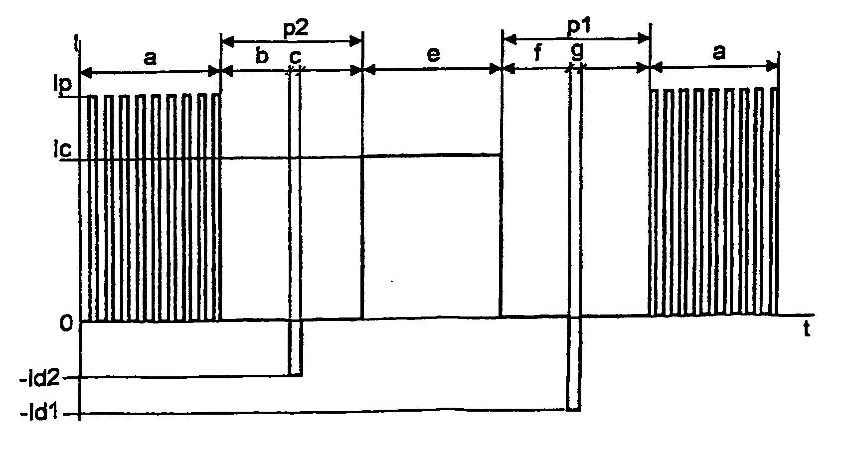
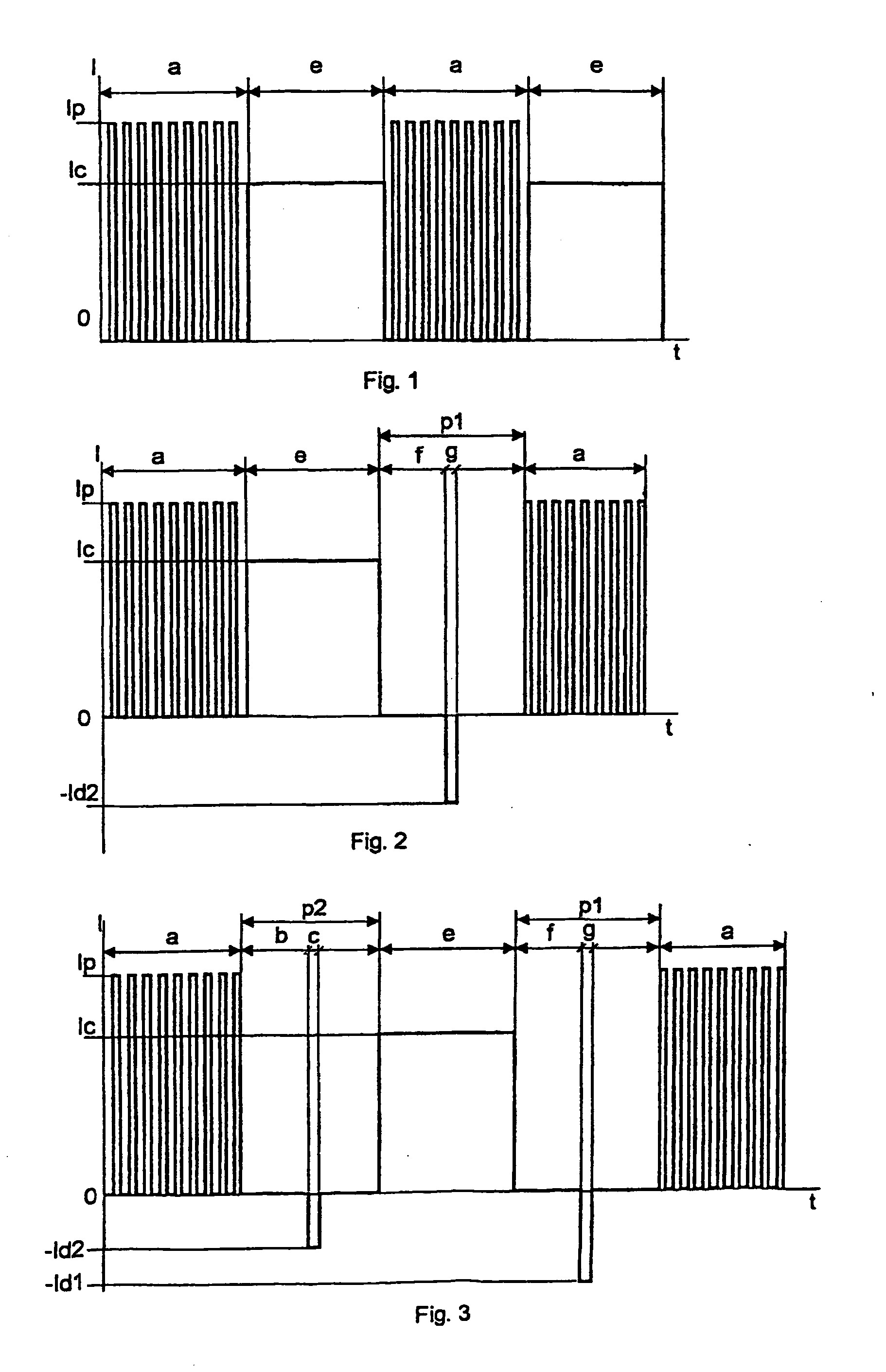
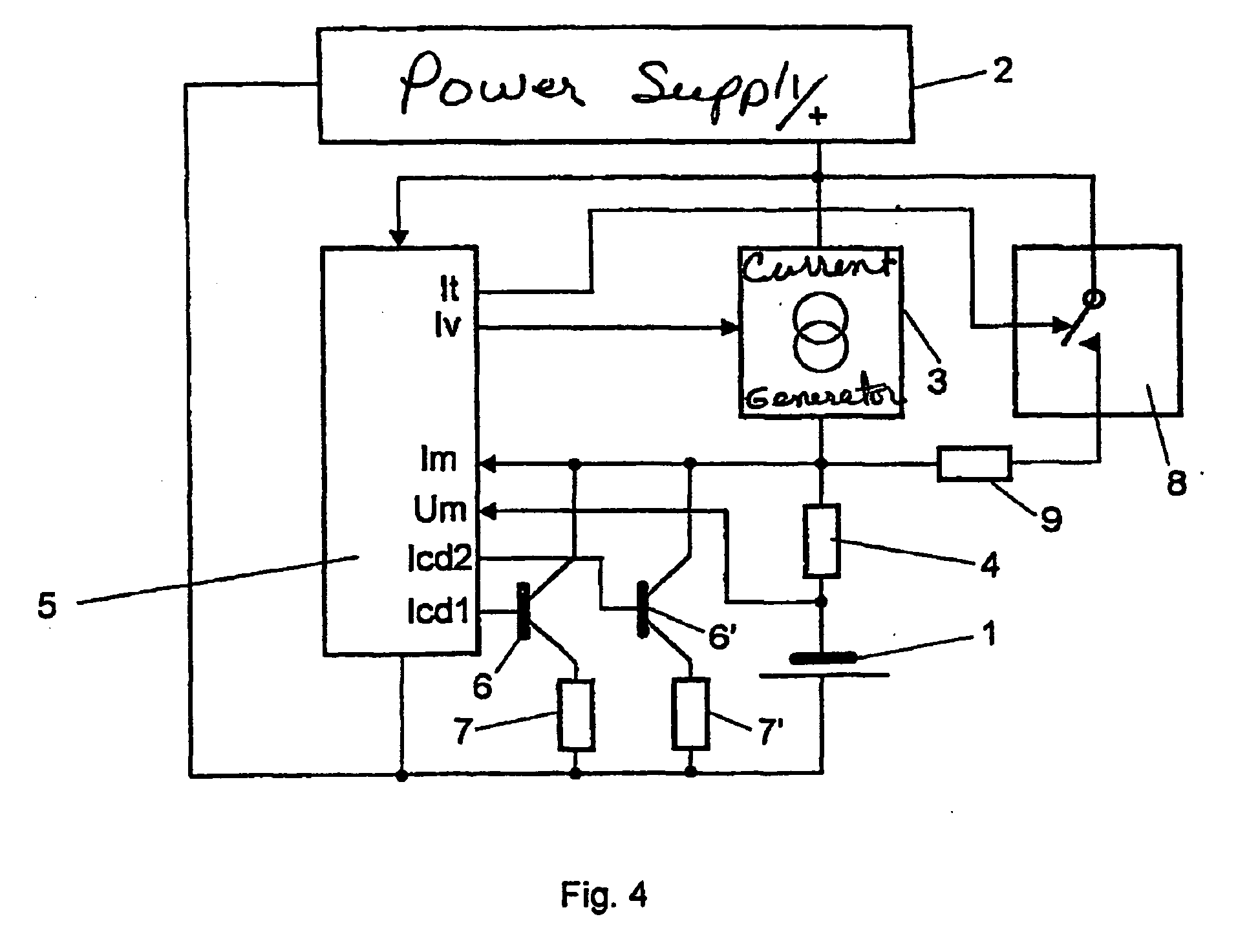
[0030]The first and simplest possible preferred method according to the invention can be followed in FIG. 1. On the horizontal axis of the graph the time t, on the vertical axis the current I applied to the terminals of the rechargeable battery are drawn up. The charging current is supplied by an electric power supply applied through a charging circuit to the terminals of the battery to be charged, which power supply can be a rectifier connected to the AC power line voltage, but any battery with higher voltage or similar may be used as well. With this embodiment there are different charging intervals inserted into the charging current, namely interval a, which is a pulsed charging interval, followed by an interval e, which is a charging interval with continuous charging current.

[0031]The interval a is a charging interval consisting of charging current pulses. The frequency of the pulse series is essentially identical with the internal resonance frequency of the rechargeable battery....


PUM

PropertyMeasurementUnit
frequencyaaaaaaaaaa
frequencyaaaaaaaaaa
resonance frequenciesaaaaaaaaaa

Abstract

The object of the invention is a method for charging a rechargeable battery having non-liquid electrolyte, which battery has an internal resonance frequency. The charging process contains at least one charging interval performed with current pulses, the frequency of said current pulses is essentially identical with the internal resonance frequency of the battery to be charged. Following the charging interval consists of periodic current pulses optionally a second relaxation interval is inserted, in which no charging current is applied to the rechargeable battery, within which optionally a second discharging interval is applied. After the second relaxation interval the charging is performed in an interval consists of a continuous charging current, whereafter an optional first relaxation interval is inserted, within which optionally a second discharging interval is applied. This sequence of the above steps can be varied and applied repeatedly until the full charge of the battery is attained.

Description

CLAIM OF PRIORITY[0001]This application is a Continuation of U.S. application Ser. No. 10 / 478,815, filed Nov. 26, 2003, entitled Method and Apparatus for Charging a Rechargeable Battery with Non-Liquid Electrolyte now U.S. Pat. No. 7,557,541 the teachings of which are incorporated herein by reference.TECHNICAL FIELD[0002]The invention relates to a method for charging a rechargeable battery having non-liquid, but for example a gel electrolyte, said battery has an internal resonance frequency. In the course of charging a charging current is applied to a battery. The invention relates furthermore to a circuit arrangement for implementing the method of charging the battery having non-liquid electrolyte, where an electric power supply is connected through a current measuring device to the battery terminals.BACKGROUND ART[0003]Several methods are known for quick charging of batteries, where the charging current is periodically interrupted and during the pause on charging a short discharge...

Claims


Application Information

Patent Timeline
Patent Type & Authority Applications(United States)
IPC IPC(8): H02J7/04H01M10/44H02J7/00
CPCH02J7/0093H02J7/00711
Inventor MARINKA-TOTH, JOZSEFREISZ, ATTILAROZSNYAY, VIKTOR
Owner MARINKA TOTH JOZSEF
Why Eureka
Try Eureka