Variable power optical system, imaging lens system and digital apparatus

a variable power, optical system technology, applied in the field of zoom optical system, can solve the problems of limited objects to be photographed, difficult to employ the lens barrel, and insufficient miniaturization of the optical system, and achieve the effect of maximal suppression of moving objects and sufficient correction of magnification chromatic aberration

Active Publication Date: 2009-12-17
KONICA MINOLTA OPTO
View PDF11 Cites 12 Cited by
  • Summary
  • Abstract
  • Description
  • Claims
  • Application Information

AI Technical Summary

Benefits of technology

[0009]In view of the above conventional disadvantages, it is an object of the present invention to provide a compact i.e. microminiaturized zoom optical system that enables to obtain a high-quality image with respect to the entirety of a captured image by sufficiently correcting magnification chromatic aberration while maximally suppressing a moving amount of lens groups for zooming, as well as an imaging lens device incorporated with the zoom optical system, and a digital apparatus loaded with the imaging lens device.
[0011]In the above arrangement, the zoom optical system is configured into a negative dominant optical system, in which the first lens group closest to the object side has a negative optical power. This enables to promptly alleviate emission of light rays incident from the object side with a large angle by the negative optical power of the first lens group. This is advantageous in reducing the entire length of the optical system or the diameter of the forwardmost lens element. Also, in the negative dominant arrangement, increase of error sensitivity can be suppressed despite miniaturization of the optical system. These advantages are particularly increased in a zoom lens device whose zoom ratio is about two to three times.
[0013]The above arrangement of the invention enables to miniaturize the zoom optical system as a negative dominant arrangement, and sufficiently correct magnification chromatic aberration or a like drawback in the second lens group, which may be involved in miniaturizing or microminiaturizing the zoom optical system, by optimizing the Abbe number of the positive lens element in the third lens group or in the lens group closer to the image side than the third lens group. The arrangement is advantageous in providing a satisfactorily miniaturized zoom optical system whose aberration is desirably corrected in the entire zoom range in a zoom optical system with a certain zoom ratio, particularly, in a zoom optical system with a zoom ratio of about two to three times.
[0016]The aforementioned arrangements of the invention enable to realize a compact, high-resolution, and zoomable imaging lens device that is mountable in a mobile phone, a personal digital assistant, or a like device, as well as a digital apparatus loaded with the imaging lens device.

Problems solved by technology

Since the magnification of the single focus optical system is substantially equivalent to visual magnification, an object to be photographed is limited to the one located near a photographer.
It is difficult to employ the lens barrel collapsible structure as recited in patent document 1 to a mobile phone or a like device, because an impact resistance required for the mobile phone or a like device is high.
Therefore, miniaturization has not been completely accomplished in the optical system disclosed in patent document 1.
In the zoom optical system recited in patent document 2, the power of the second lens group is weak, and the optical system is not compact because of a large moving amount.
In light of these drawbacks, it is difficult to mount the zoom optical system recited in patent document 2 in a mobile phone or a like device.
In this case, particularly at a telephoto end, magnification chromatic aberration resulting from an increase in optical power of the second lens group is unduly increased, which may lower the contrast in the periphery of a captured image, and resultantly cause image degradation.

Method used


Image

  • Variable power optical system, imaging lens system and digital apparatus
  • Variable power optical system, imaging lens system and digital apparatus
  • Variable power optical system, imaging lens system and digital apparatus

Examples


example 1

[0164]FIG. 6 is a cross-sectional view i.e. an optical path diagram, taken along the optical axis (AX), showing an arrangement of lens groups in a zoom optical system 100A as Example 1. The optical path diagrams in FIG. 6, and FIGS. 7 through 24 to be described later each shows a lens arrangement at the wide angle end (W). Throughout Example 1, and Examples 2 through 18 to be described later, the lens groups include, in this order from the object side in the drawings i.e. the left side in FIG. 6, a first lens group (Gr1) having a negative optical power as a whole, a second lens group (Gr2) having a positive optical power as a whole, and a third lens group (Gr3) having a positive or negative optical power as a whole. In other words, the lens arrangement is a negative dominant arrangement, in which the first lens group closest to the object side has a negative optical power.

[0165]The zoom optical system 100A in Example 1 shown in FIG. 6 has the following lens group arrangement in the ...

example 2

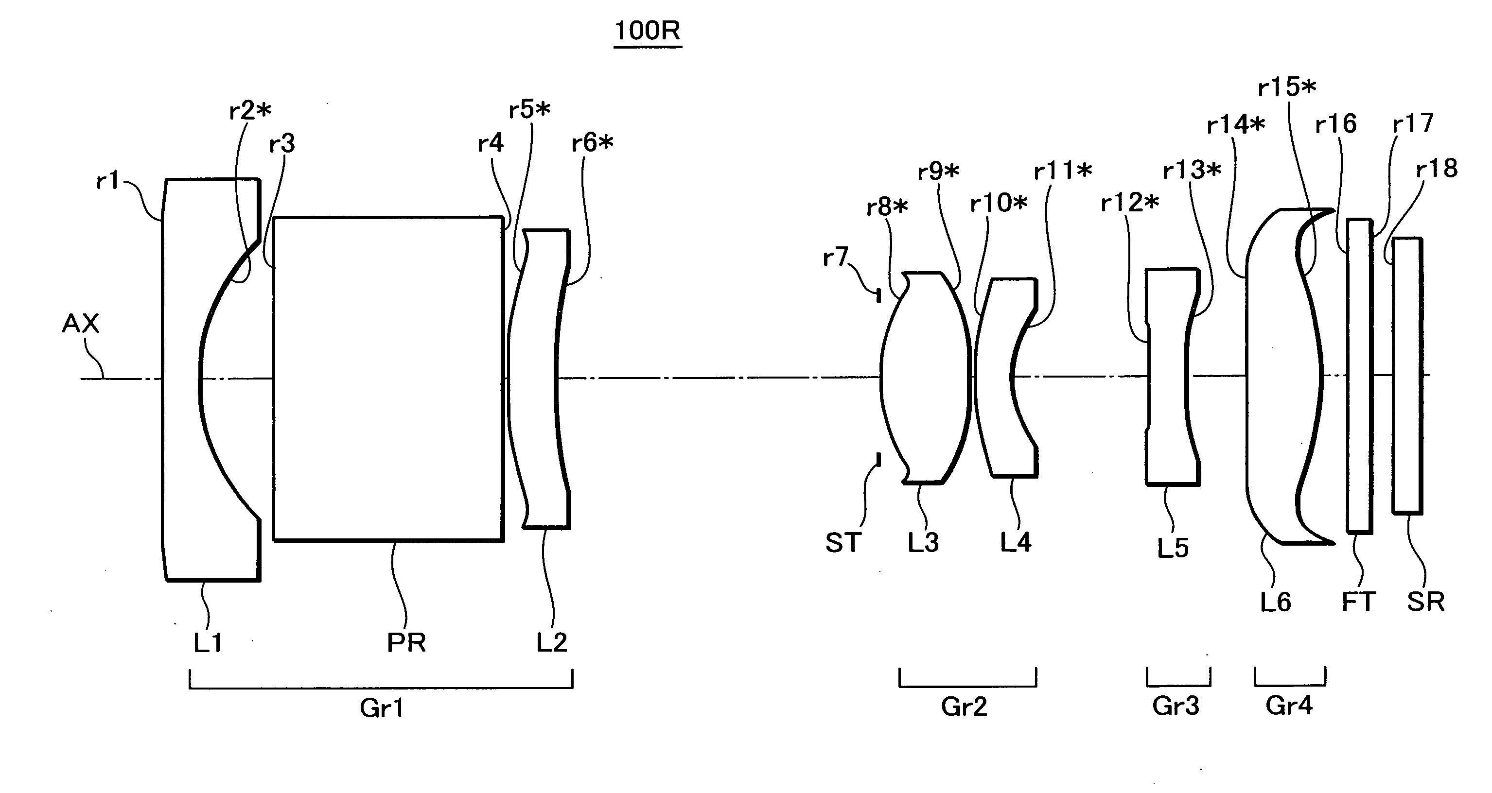
[0182]FIG. 7 is a cross-sectional view, taken along the optical axis (AX), showing an arrangement of lens groups in a zoom optical system 100B as Example 2. The zoom optical system 100B in Example 2 includes, in the order from the object side, a first lens group (Gr1) having a negative optical power, an aperture stop (ST) arranged on the object side of a second lens group (Gr2), the second lens group (Gr2) having a positive optical power as a whole, a third lens group (Gr3) having a positive optical power, and a fourth lens group (Gr4) having a negative optical power. More specifically, the first lens group (Gr1) is constituted of a biconcave negative lens element (L1) and a positive meniscus lens element (L2) convex to the object side in this order from the object side. The second lens group (Gr2) is constituted of a biconvex positive lens element (L3) and a biconcave negative lens element (L4). The third lens group (Gr3) is constituted of a positive meniscus lens element (L5) conv...

example 3

[0185]FIG. 8 is a cross-sectional view, taken along the optical axis (AX), showing an arrangement of lens groups in a zoom optical system 100C as Example 3. The zoom optical system 100C in Example 3 includes, in the order from the object side, a first lens group (Gr1) having a negative optical power as a whole, an aperture stop (ST) arranged on the object side of a second lens group (Gr2), the second lens group (Gr2) having a positive optical power as a whole, and a third lens group (Gr3) having a positive optical power. More specifically, the first lens group (Gr1) is constituted of a biconcave negative lens element (L1) and a positive meniscus lens element (L2) convex to the object side in this order from the object side. The second lens group (Gr2) is constituted of a biconvex positive lens element (L3) and a negative lens element (L4) convex to the object side in this order from the object side. The third lens group (Gr3) is constituted of a positive meniscus lens element (L5) c...


PUM


Abstract

Provided is a microminiaturized zoom optical system capable of sufficiently correcting aberration. The zoom optical system (100) includes a first lens group (101) having a negative optical power, a second lens group (102) having a positive optical power, and a third lens group (103) having a positive or negative optical power in this order from the object side. The zoom optical system is configured in such a manner that the interval between the first lens group (101) and the second lens group (102) is decreased in zooming from the wide angle end to the telephoto end. A positive lens element in the third lens group (103) or in a lens group closer to the image side than the third lens group (103) satisfies the following conditional expression:vp<40where vp is the minimum value of the Abbe number of the positive lens element.

Description

TECHNICAL FIELD[0001]The present invention relates to a zoom optical system constituted of lens groups for zooming by changing the interval between the lens groups in the optical axis direction, an imaging lens device incorporated with the zoom optical system, and a digital apparatus loaded with the imaging lens device, and more particularly to a zoom optical system or a like device adapted for miniaturization.BACKGROUND ART[0002]In recent years, mobile phones or PDAs (Personal Digital Assistants) have been widespread. Also, the specifications in which a compact digital still camera unit or a compact digital video unit is incorporated in the mobile phone or the PDA have been generalized. In a digital apparatus such as the mobile phone or the PDA, a small-sized image sensor with a low pixel number, as compared with an independent product such as a digital still camera, and an imaging lens device provided with a single focus optical system constituted of one to three plastic lens elem...

Claims


Application Information

Patent Timeline
Patent Type & Authority Applications(United States)
IPC IPC(8): G02B15/14
CPCG02B15/177G02B15/143503G02B15/143507G02B15/144507G02B15/144511
Inventor MATSUSAKA, KEIJIOHZAWA, SOH
Owner KONICA MINOLTA OPTO
Why Eureka
Try Eureka