Flow-Through Air Conditioning for Electronics Racks

a technology for electronics racks and air conditioners, applied in domestic cooling apparatuses, cooling/ventilation/heating modifications, casings/cabinets/drawers, etc., can solve the problem of not having access to chilled air sources, and achieve the effect of reducing power input requirements

Inactive Publication Date: 2009-12-17
MINEBEA CO LTD
View PDF23 Cites 45 Cited by
  • Summary
  • Abstract
  • Description
  • Claims
  • Application Information

AI Technical Summary

Benefits of technology

[0011]The flow-through configuration of the present invention allows the cooling system to operate

Problems solved by technology

Small centers and small/mid-size businesses using single stand-alone racks,

Method used


Image

  • Flow-Through Air Conditioning for Electronics Racks
  • Flow-Through Air Conditioning for Electronics Racks
  • Flow-Through Air Conditioning for Electronics Racks

Examples


Embodiment Construction

[0021]Details of embodiments of the present invention will now be discussed to illustrate the best mode contemplated by the inventor for practicing the present invention, including variations thereof. Structural elements common among the figures are represented by common reference numerals. It will be evident from the explanations that alternatives and substitutions can be made without departing from the scope and spirit of the present invention.

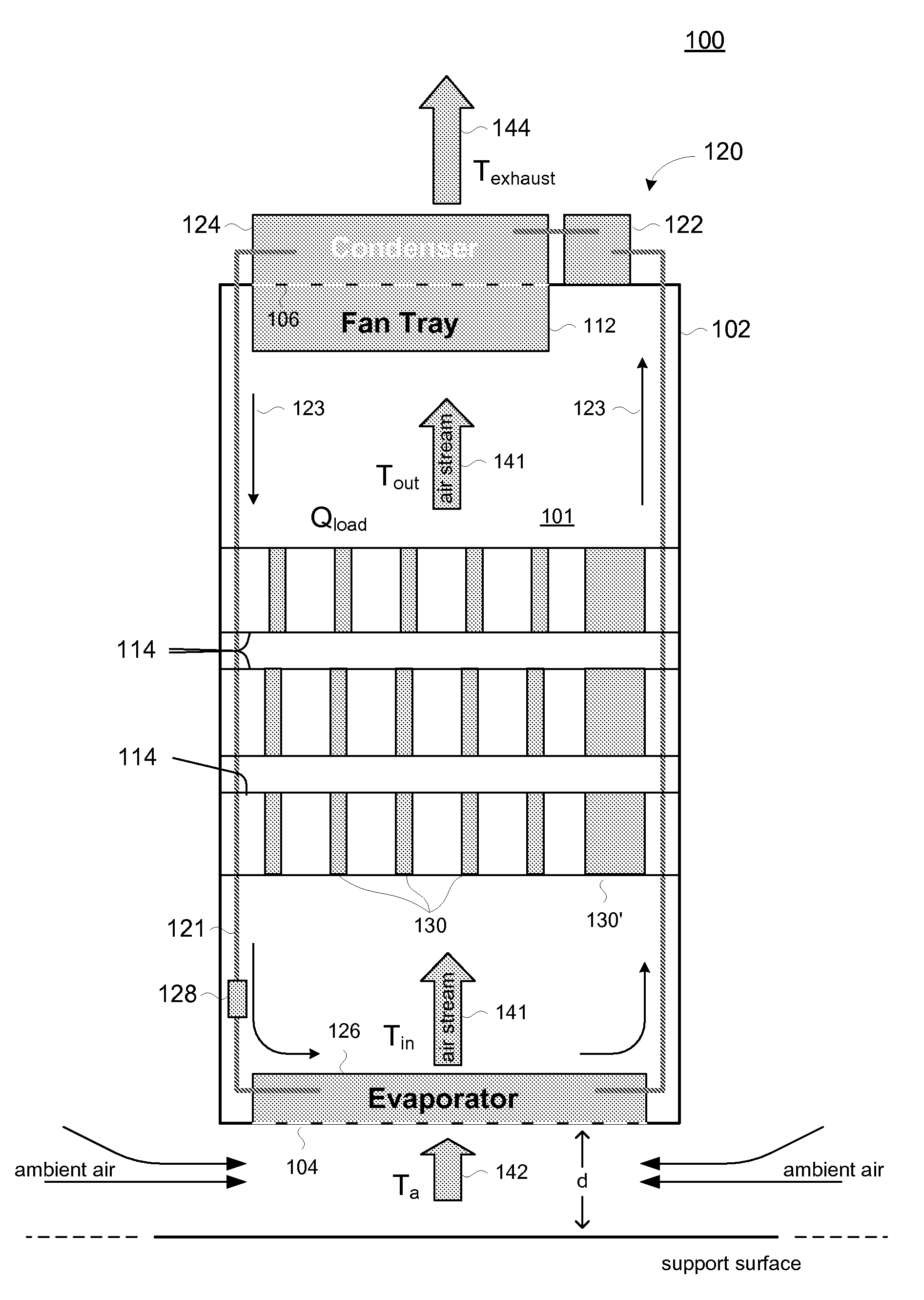
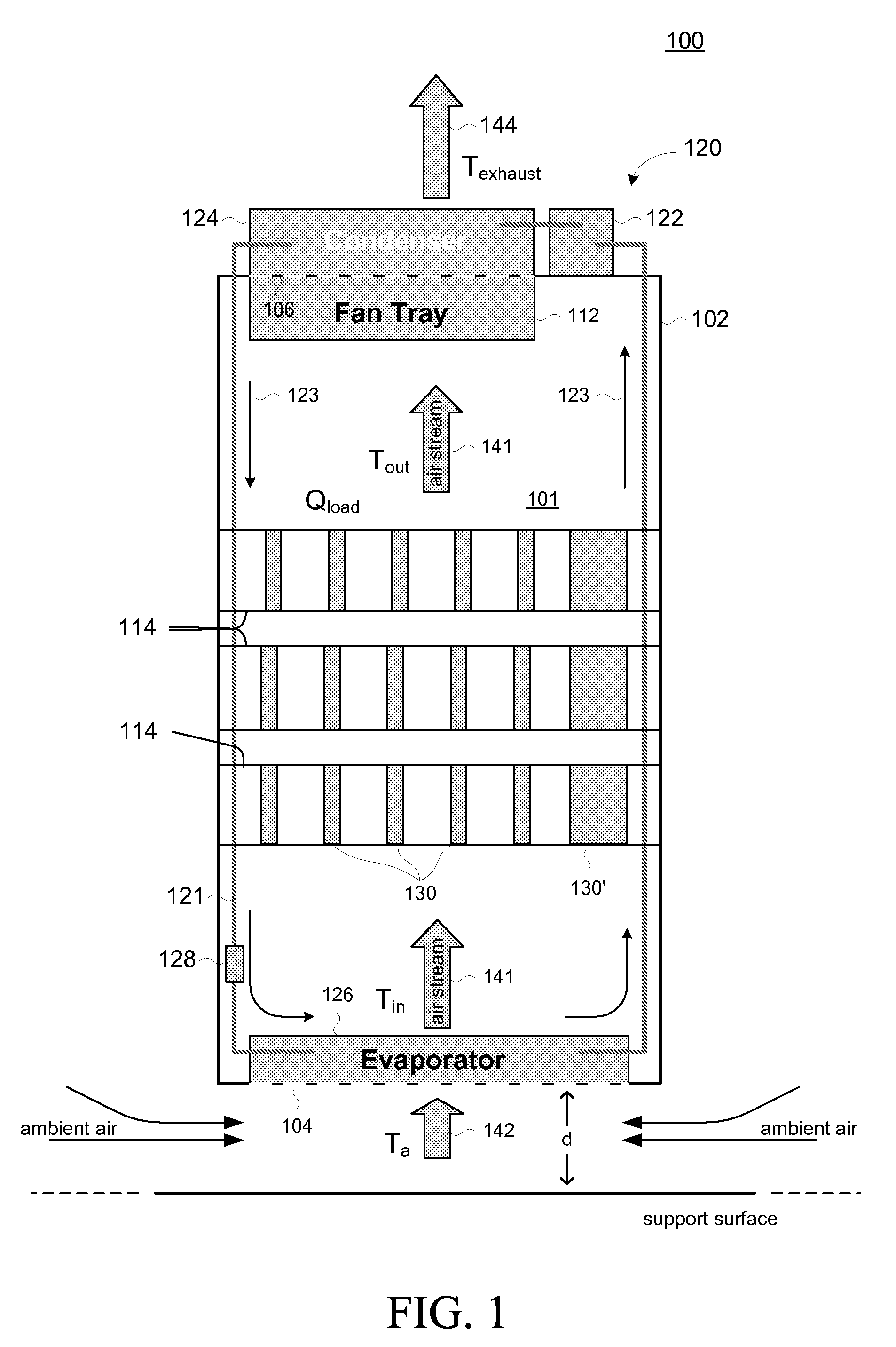
[0022]An illustrative embodiment of the present invention is explained in connection with a schematic representation of an electronics cabinet 100 as shown in FIG. 1. It is noted that while embodiments of the present invention are described in the context of cabinets for housing electronic equipment (referred to variously as electronics racks, enclosures and so on), it will be readily apparent from the teachings in the figures and the disclosure that the present invention can be used to house equipment and objects other than electronics equi...


PUM


Abstract

A cabinet adapted with a cooling system is described. Embodiments include electronics cabinets which house electronic equipment. A flow of air is set up in the interior of the cabinet by drawing in ambient air. The incoming air is cooled by an evaporator component of a cooling system. The cooled air cools the electronics and in the process becomes heated air. The heated air serves to cool a condenser component of the cooling system, thereby further heating the heated air. The heated air is then exhausted from the cabinet.

Description

BACKGROUND OF THE INVENTION[0001]The present invention is directed generally to a cooling systems, and in particular to methods and apparatus for removing heat from cabinets for supporting electronics equipment.[0002]Electronic equipment is typically housed in units referred to variously as electronics cabinets, rack-mount electronic enclosures, electronics racks, and so on. An electronics cabinet typically comprises an enclosure housing electronic devices or components, usually assembled on large printed circuit cards (sometimes referred to as modules) inserted into slots of a card rack. Auxiliary components such as power supplies, power conditioning circuits, and the like are also typically included in the enclosure or housing.[0003]To cool the electronic equipment, fans or blowers, most often positioned in trays, force air over the cards to remove the heat produced by the electronics. FIGS. 7A and 7B, for example, show a typical electronics cabinet 700. The enclosure 702 houses v...

Claims


Application Information

Patent Timeline
IPC IPC(8): H05K5/02F25D15/00
CPCH05K7/20681
Inventor CHRYSLER, GREGORY M.
Owner MINEBEA CO LTD
Why Eureka
Try Eureka