Contactless conductivity detector

a conductivity detector and contactless technology, applied in the direction of material analysis by electric/magnetic means, measurement devices, instruments, etc., can solve the problems of sudden change in zero leveled output voltage or peak in daq graph, not fully met, and not easily made portable by optical detectors. , to achieve the effect of improving sensitivity and detection limit, improving sensitivity, and reducing power inputs

Inactive Publication Date: 2011-06-16
AGENCY FOR SCI TECH & RES
View PDF13 Cites 7 Cited by
  • Summary
  • Abstract
  • Description
  • Claims
  • Application Information

AI Technical Summary

Benefits of technology

[0040]As will be appreciated from the above summary, specific aspects of the present invention provide a C4D cell with improved sensitivity and detection limit compared to detection cells of the state of the art. A benefit of improving sensitivity is that the present invention can be implemented using lower power inputs than previously employed. The gap distance between the detection electrodes is made adjustable in accordance with certain embodiments of the invention, hence the detection cell length and thus the limit of detection (LOD, which determines sensitivity) and / or peak separation (which determines resolution) can be fine-tuned depending on demands of the specific application Where a shielded housing is provided containing all the necessary electronics and the C4D cell, an enhanced signal-to-noise ratio (S / N) is able to be obtained, which results in a highly sensitive electrophoretic device. Embodiments of the present invention also provide a C4D detection device that has low power requirements. These and other related advantages will be readily apparent to skilled persons from the description below.

Problems solved by technology

To this date, these conditions have not been fully met and detection remains the main challenge in the development of LOC technology.
However, optical detectors are not universal and not easily made portable due to the size of the light sources.
In practical terms, this leads to a sudden change in the zero leveled output voltage or a peak in the DAQ graph.
In this configuration, the capacitance coupling to the solution in the channel 102 is inefficient and requires a high frequency and high voltage to couple the signal to detect low concentration samples.
High frequencies, however, result in stray capacitance having a more significant effect.
However, while these strategies decrease the stray capacitance somewhat, the resulting detection sensitivity remains limited.
However, high voltage levels are difficult to produce and are not safe to handle in portable systems.
Another option to have increased capacitance is to use relatively large electrodes or detection lengths, but these approaches severely decrease resolution.
These approaches are either inaccurate (for option (i) above) or require complex fabrication processes (for option (ii) above).

Method used


Image

  • Contactless conductivity detector
  • Contactless conductivity detector
  • Contactless conductivity detector

Examples


Embodiment Construction

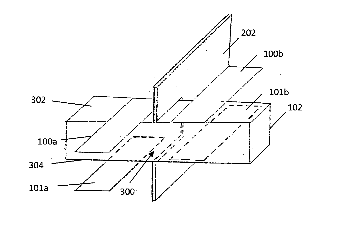
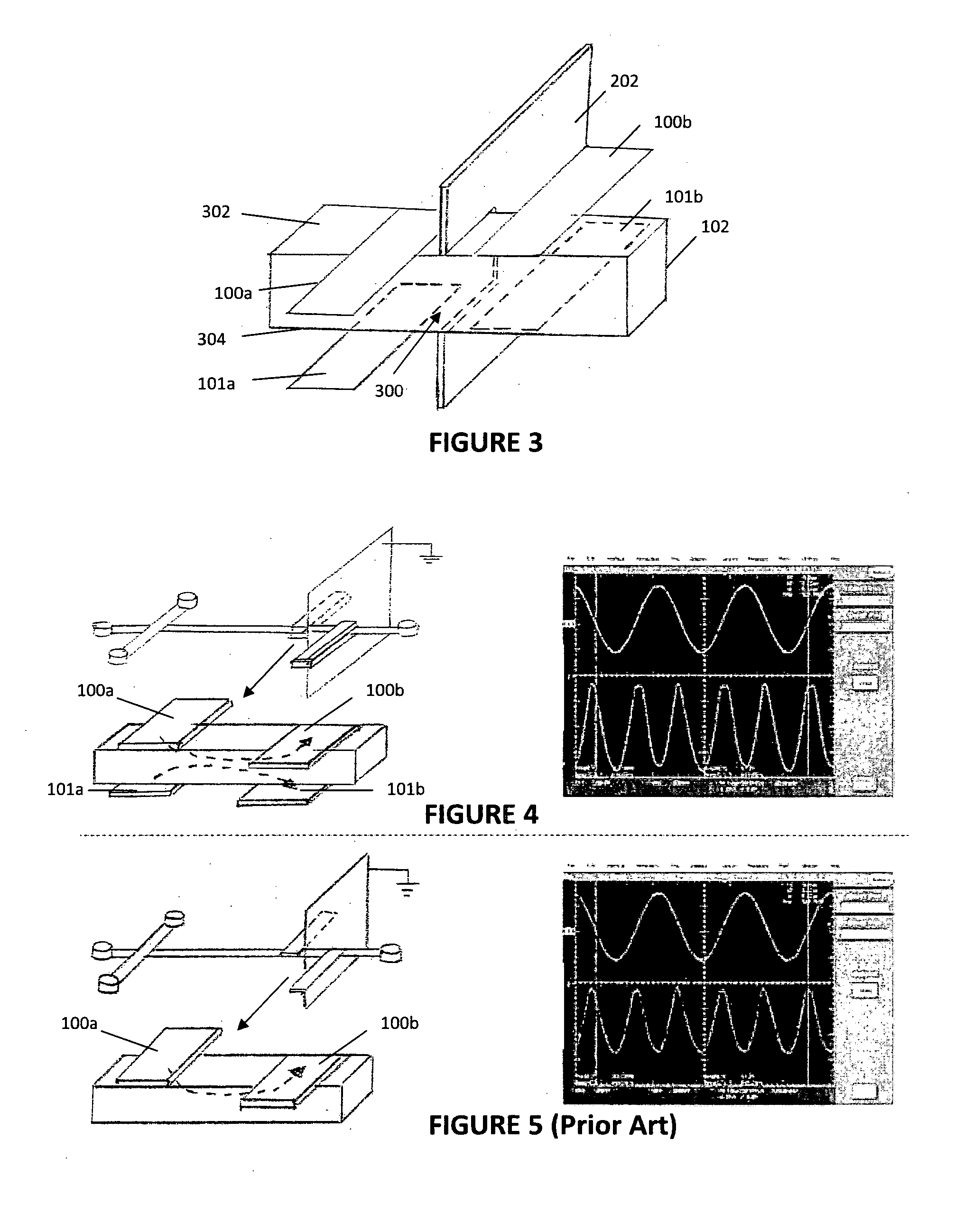
[0063]Referring to FIG. 3, the present invention in one preferred embodiment comprises a capacitively-coupled contactless conductivity detector comprising a microfluidic electrophoretic chip (not shown) having a separation channel 102 thereon, first and second emitting electrodes 100a, 101a, and first and second receiving electrodes 100b, 101b on the chip and adjacent the separation channel 102. Between the emitting electrodes 100a, 101a and the receiving electrodes 100b, 101b is a detection area generally indicated with arrow 300. As will be described in detail below, the first and second emitting electrodes 100a, 101a are configured to concentrate signals emitted from one another to the detection area 300, and the first and second receiving electrodes 100b, 101b are configured to extract signals from the detection area 300.

[0064]It can be seen from FIG. 3 that the separation channel 102 is defined by channel walls, with the first emitting electrode 100a and the first receiving ele...


PUM


Abstract

The contactless conductivity detector in one embodiment includes a microfluidic chip having a channel (102) thereon and four detection electrodes: first and second emitting electrodes (100a, 101a), and first and second receiving electrodes (100b, 101b). The channel (102) is defined by channel walls. The first emitting electrode (100a) and the first receiving electrode (100b) are adjacent a first channel wall, and the second emitting electrode (101a) and the second receiving electrode (101b) are adjacent a second channel wall, the second channel wall being opposite the first channel wall.

Description

FIELD OF THE INVENTION[0001]The present invention relates to a contactless conductivity detector, and more particularly, but not exclusively, to a device for analysing and detecting analytes or ionic compounds using capacitively-coupled contactless conductivity detection (C4D).BACKGROUND OF THE INVENTION[0002]Lab-on-a-chip (LOC) based device requirements for analyte detection are sensitivity, universality and portability. To this date, these conditions have not been fully met and detection remains the main challenge in the development of LOC technology. Optical detectors, including fluorescence detection, have demonstrated the highest sensitivity. However, optical detectors are not universal and not easily made portable due to the size of the light sources. The use of electrochemical methods is well-suited for integration into portable systems, but they are less sensitive and prone to interferences. From the group of electrochemical sensors, C4D detectors are the most appealing as t...

Claims


Application Information

Patent Timeline
Patent Type & Authority Applications(United States)
IPC IPC(8): G01R27/26
CPCG01N27/4473G01N27/44791
Inventor MAHABADI, KAMBIZ ANSARIRODRIGUEZ FERNANDEZ, ISABELLIM, CHEE YEN
Owner AGENCY FOR SCI TECH & RES
Why Eureka
Try Eureka