Multi-stack flywheel energy storage assembly

a flywheel and energy storage technology, applied in mechanical energy handling, electrical equipment, dynamo-electric machines, etc., can solve the problems of significant cost and safety, significant time and power required to charge and recharge a heavy flywheel, and higher speeds

Inactive Publication Date: 2014-04-17
DUGAS PATRICK J
View PDF3 Cites 7 Cited by
  • Summary
  • Abstract
  • Description
  • Claims
  • Application Information

AI Technical Summary

Benefits of technology

[0013]This design solves several of the problems identified in the ‘prior art’ section of this application. The sequential startup of a series of lighter flywheels allows the use of smaller motor / generators, reduces the power input required to activate the flywheel assembly, and / or allows the entire assembly of flywheels to fully activate in less time than required by the conventional heavy flywheel. The discharge problem of a partially charged flywheel is solved because in this assembly, the non-charged flywheels never couple to the drive shaft and thereby present no drag on the drive shaft or the charged flywheels now coupled to the shaft.Three Embodiments-Described

Problems solved by technology

One problem with prior art is the significant amount of time and power required to charge and recharge a heavy flywheel.
A second problem associated with prior art is encountered when the heavy flywheel is discharged prior to attaining its optimum operating speed (full charge).
The Higher speeds have presented significant expense and safety issues.

Method used


Image

  • Multi-stack flywheel energy storage assembly
  • Multi-stack flywheel energy storage assembly
  • Multi-stack flywheel energy storage assembly

Examples


first embodiment

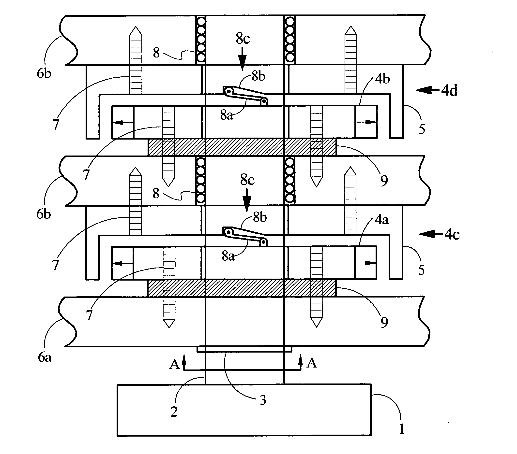
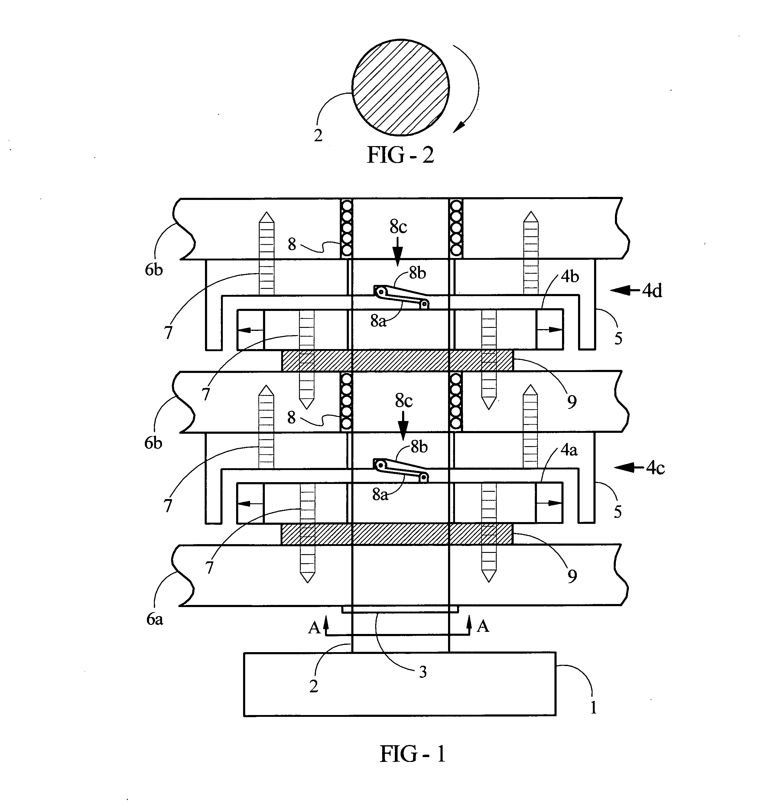
[0026]The first embodiment, as illustrated in FIG. 1 is especially suited to a fixed or permanent installation in a power generation facility, a wind farm or a solar collector installation. An electrical power source (not shown) supplies power to an electric motor / generator 1. Said motor / generator is an electric motor, able to be mechanically driven so as to act as an electric generator. A drive shaft 2 extends from said motor / generator 1 as a one piece drive shaft of sufficient length to accommodate a plurality of flywheels. The first flywheel 6a is securely attached to said drive shaft 2 by a collar 3 or other suitable method of attachment so that when power is supplied to said motor / generator 1, said first flywheel 6a and said drive shaft 2 begins to charge or spin. While said drive shaft 2 and said first flywheel 6a continue to accelerate, a second and all subsequent flywheels 6b remain motionless as said drive shaft 2 rotates within each of said flywheels 6b without imparting a...

second embodiment

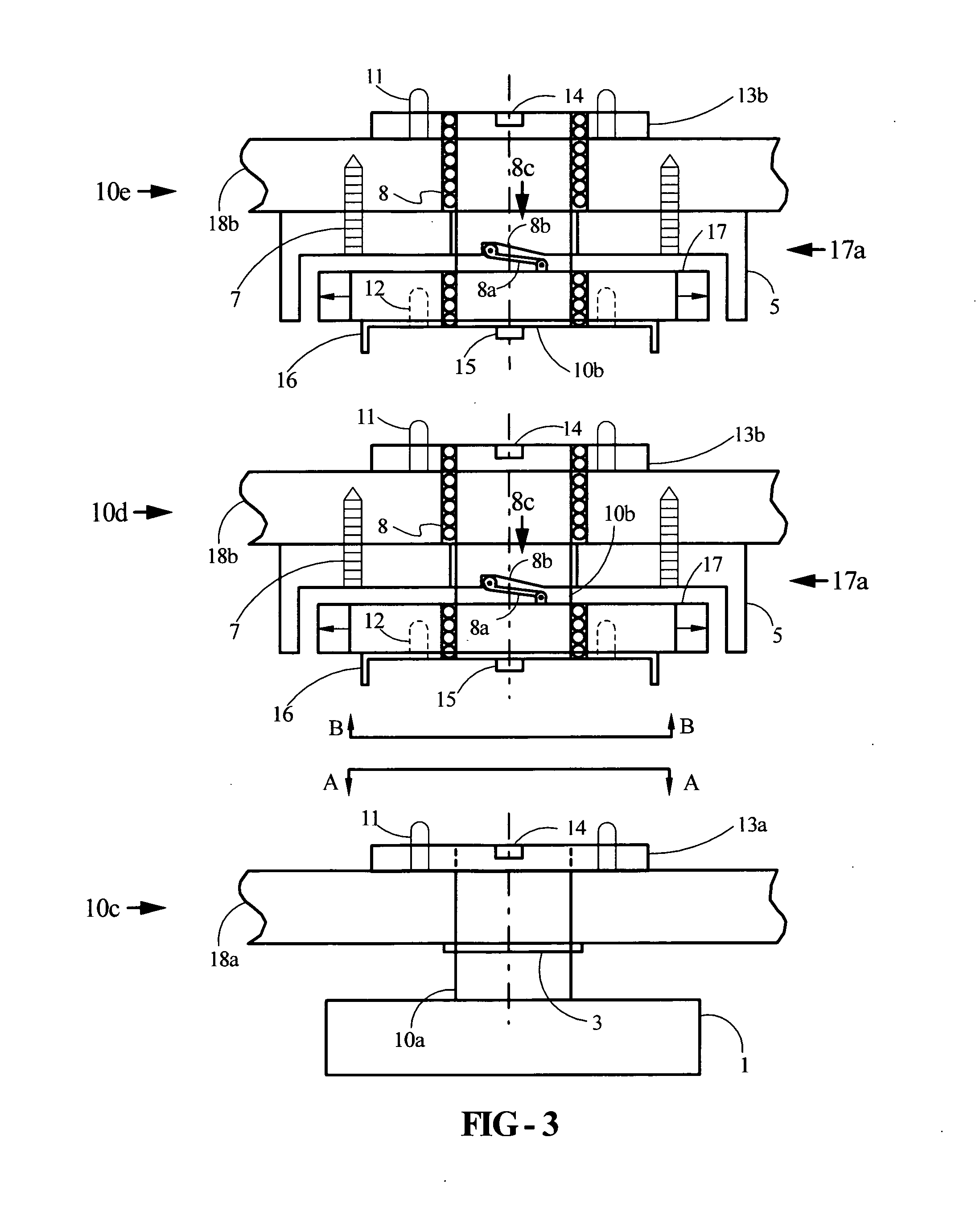
[0029]The second embodiment, as illustrated in FIG. 3 illustrates a first flywheel assembly 10c, a second flywheel assembly 10d and a third flywheel assembly 10e. Additional flywheel assemblies are anticipated to be added as needed, but only these are illustrated for simplicity. Said first flywheel assembly 10c includes a motor / generator 1 which incorporates a first drive shaft section 10a that extends from said motor / generator 1, to a length sufficient to accommodate a first flywheel 18a. Said first flywheel 18a is securely attached to said first drive shaft section 10a via a collar 3 or other suitable method of attachment. When electric power is supplied to said motor / generator 1, said first flywheel 18a begins to charge or spin. Mounted to said first flywheel 18a is a first connecting spacer 13a. Said spacer 13a incorporates a square female notch 14 and a connector pins 11. This completes the operation of said first flywheel assembly 10c.

[0030]The second flywheel assembly 10d in...

third embodiment

[0037]The third, and preferred embodiment substitutes a variable inertia flywheels 19 in place of all flywheels referenced in the first and second embodiment. The Variable Inertia Flywheel (of Pub. No.: US 2011 / 0277587 A1) anticipates faster spin-up times compared to a conventional flywheel of same weight and diameter, but at full charge, provides an equal amount of energy storage as the conventional flywheel.


PUM


Abstract

A flywheel based energy storage system which includes multiple flywheels and a motor / generator unit. A single flywheel is fixed to the drive shaft. Multiple additional flywheels are mounted to drive shaft via bearings to allow freewheeling. Fixed flywheel is fully charged before speed activated clutch engages second flywheel. All additional flywheels are started sequentially in like manner. During discharge, charged flywheels engage drive shaft via one-way ratchet type mechanism and non-charged flywheels continue to freewheel. A sectional drive shaft of one embodiment simplifies portability and assembly. A Variable inertia flywheel of another embodiment further reduces charge-up time.

Description

[0001]This application is a continuation-in-part of U.S. patent application Ser. No. 12 / 690,397 filed Jan. 20, 2010.TECHNICAL FIELD[0002]This invention relates to flywheel energy storage devices that store energy from any electrical grid or other energy source such as wind turbines and photovoltaic solar power to a flywheel assembly.BACKGROUND OF THE INVENTION[0003]1. Field of Invention[0004]This invention relates to flywheels, specifically to an improved coupling / starting and discharge mechanism for multiple flywheels, allowing sequential start-up / recharge, and also provides simultaneous discharge of only the charged or partially charged flywheels.[0005]2. Background-Discussion of Prior Art[0006]Flywheels have been used to store energy from power sources for years. Existing flywheel technology consists of a heavy rotating disc that is accelerated to its optimum speed by an electric motor, able to be mechanically driven so as to act as an electric generator. Electricity is stored as...

Claims


Application Information

Patent Timeline
Patent Type & Authority Applications(United States)
IPC IPC(8): H02K7/02H02K15/00H02K7/10
CPCH02K7/025H02K15/0006H02K7/10H02K7/108Y02E60/16
Inventor DUGAS, PATRICK J.
Owner DUGAS PATRICK J
Why Eureka
Try Eureka