
Straw filamentation machine

A straw and protective mechanism technology, applied in agricultural machinery and tools, cutting equipment, applications, etc., can solve the problems of poor applicability, small power input, and easy material accumulation of whole straw and bundled straw, and meet the needs of decentralized operations The effect of small demand, small power input, and light structure

Active Publication Date: 2019-12-20
SHENYANG AGRI UNIV
View PDF4 Cites 8 Cited by
  • Summary
  • Abstract
  • Description
  • Claims
  • Application Information

AI Technical Summary

Problems solved by technology

[0004] In order to solve the problems of poor applicability, large volume, high power consumption, and easy material accumulation of existing straw silking equipment for whole plant straws and bundled straws, the present invention innovatively provides a straw silking machine. The machine adopts the cooperative operation method of feeding and dividing, cutting and crushing, and hammering and kneading to realize the silk treatment of straw. It can be applied to whole straw and bundled straw at the same time. The structure is light and simple, small in size, small in power input, and high in efficiency.

Method used


Image

  • Straw filamentation machine
  • Straw filamentation machine
  • Straw filamentation machine

Examples


Embodiment Construction

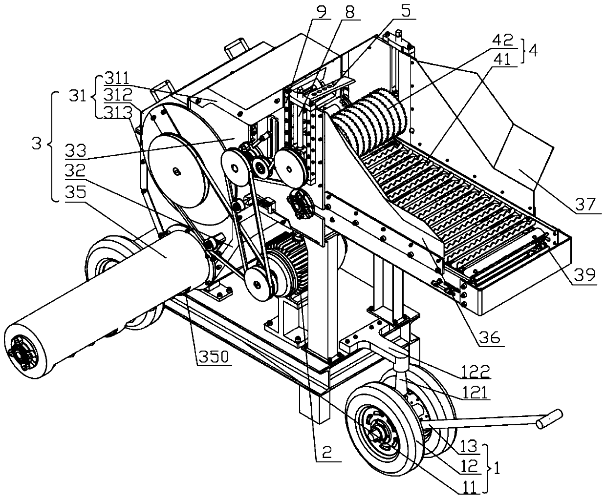
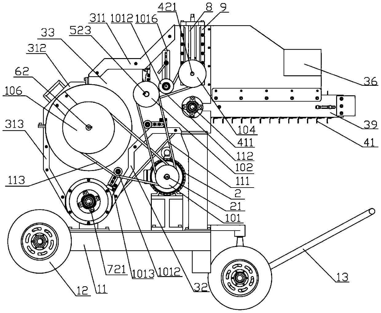
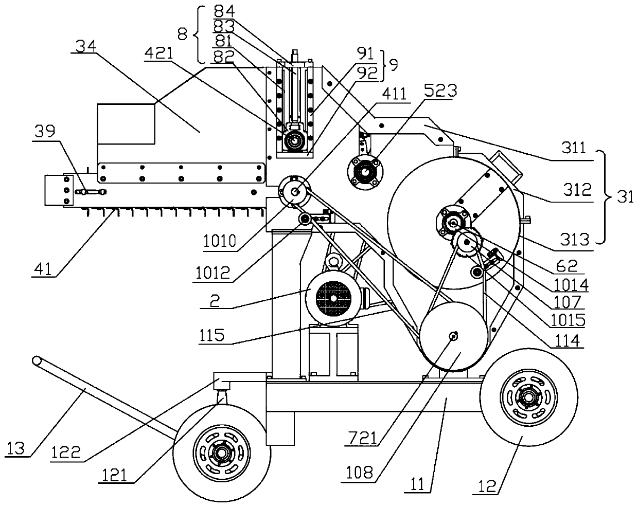
[0046] The straw silking machine provided by the present invention will be explained and described in detail below in conjunction with the accompanying drawings of the description.

[0047] Such as Figure 1~5 As shown, this embodiment specifically discloses a straw silk machine, which includes a support mechanism 1 and a drive mechanism 2 arranged on the support mechanism 1, a protection mechanism 3, a feeding mechanism 4, and a shredding mechanism 5 , knead silk mechanism 6 and discharge mechanism 7. The protection mechanism 3 forms the feeding port, the movement channel and the discharge port of the straw, the feeding mechanism 4 is fixed at the feeding port, the chopping mechanism 5 and the kneading mechanism 6 are arranged in the straw movement channel, and the discharging mechanism 7 is connected with the straw The moving passages are connected, and the straw silkized in the straw moving passage is sent out of the straw silking machine through the discharge port. The s...


PUM


Abstract

The invention discloses a straw filamentation machine. The straw filamentation machine comprises a supporting mechanism, a driving mechanism, a protection mechanism, a feeding mechanism, a shredding mechanism, a filament rubbing mechanism and a discharging mechanism, wherein the driving mechanism, the protection mechanism, the feeding mechanism, the shredding mechanism, the filament rubbing mechanism and the discharging mechanism are arranged on the supporting mechanism. A feeding hole, a straw moving channel and a discharging hole are formed in the protection mechanism; the feeding mechanismis located at the feeding hole and includes a conveyor belt and a saw disc knife roller; straw is conveyed to the shredding mechanism after being primarily crushed; the shredding mechanism and the filament rubbing mechanism are located in the straw moving channel; the shredding mechanism comprises a fixed cutter and a hob cutter, and the straw is shredded under the sliding cutting action of the fixed cutter and the hob cutter and is conveyed to the filament rubbing mechanism; the filament rubbing mechanism is used for filamentation of the shredded straw and for conveying straw filaments to thedischarging mechanism; after being screened through the discharging mechanism, the straw filaments are sent out of the machine through the discharging hole. According to the straw filamentation machine, filamentation of the straw is achieved through cooperation of feeding and division, cutting and crushing, hammering and rubbing, the filamentation efficiency is high, material accumulation is avoided, the structure is very simple, and the requirement of decentralized operation of agricultural production is met.

Description

technical field [0001] The invention relates to the technical field of straw processing, and more specifically, the invention relates to a straw silking machine. Background technique [0002] Straw silking treatment is the basic work of various technologies for the comprehensive utilization of crop straws, and the effect of silking directly affects the effect of comprehensive utilization of straws. At present, there are two types of equipment commonly used in the market to realize straw silking, the guillotine type and the hammer type. The guillotine type is divided into a disc type and a drum type according to the cutting method of the moving blade. For guillotine-cut straw silking equipment, the straight-blade hob-type cutting has very poor ability to capture the cut straw instantaneously, and the high-speed rotating cutter will generate a large tangential force and centrifugal force on the cut straw. Affect the subsequent kneading of the straw; however, when the single h...

Claims


Application Information

Patent Timeline
Patent Type & Authority Applications(China)
IPC IPC(8): A01F29/02A01F29/04A01F29/09A01F29/10
CPCA01F29/005A01F29/02A01F29/04A01F29/09A01F29/10
Inventor 王铁军王铁良王瑞丽宫元娟田素博于帅
Owner SHENYANG AGRI UNIV
Learn More