Eureka AIR delivers breakthrough ideas for toughest innovation challenges, trusted by R&D personnel around the world.

Discoloration indicators for checking life span of desulfurization disorbent, and desulfurization reactor and desulfurization system comprising the same

a desulfurization disorbent and indicator technology, which is applied in the direction of liquid-gas reaction process, thin-film type liquid gas reaction, instruments, etc., can solve the problems of reducing the activity of catalysts, and easy poisoning of catalysts, so as to facilitate the replacement time of desulfurization adsorbents

Active Publication Date: 2009-12-17
SK INNOVATION CO LTD
View PDF7 Cites 12 Cited by
  • Summary
  • Abstract
  • Description
  • Claims
  • Application Information

AI Technical Summary

Benefits of technology

The present invention relates to a discoloration indicator for checking the life span of a desulfurization adsorbent used in a desulfurization reactor for removing organic sulfur compounds from natural gas or LPG. The invention also provides a desulfurization reactor and system for preparing hydrogen or synthesis gas through steam reforming. The technical effect of the invention is to enable the simple and rapid replacement of the desulfurization adsorbent without the need for high temperatures and complicated procedures, which can be advantageous for hydrogen generators and distributed fuel cell power generation systems.

Problems solved by technology

Although the organic sulfur compound odorant is required in the interest of preventing gas leakage accidents from becoming severe, in the case where natural gas or LPG is used as feed stock for hydrogen or synthesis gas, a poisoning phenomenon, which gradually decreases the activity of the catalyst during steam reforming, is caused.
As such, there are reports that these catalysts are easily poisoned by sulfur and sulfur compounds are formed on the catalyst surface thereof at concentrations as low as ppm or less (McCarty et al; J. Chem. Phys. Vol. 72, No. 12, 6332, 1980, J. Chem. Phys. Vol. 74, No. 10, 5877, 1981).
Thus, in the case where the fuel is used to prepare hydrogen or synthesis gas through steam reforming, the steam reforming catalyst is poisoned by sulfur, undesirably decreasing the activity of the catalyst.
However, because hydrodesulfurization and subsequent absorption are conducted at high temperatures of about 300˜450° C., a long period of time is taken to increase the temperature of the catalyst or absorbent, and furthermore, upon application to steam reforming, because some of the hydrogen prepared using a steam reformer is refluxed and then fed into a desulfurization reactor, the procedure thereof is complicated.
Such operational problems may adversely affect hydrogen generators for residential fuel cell power generation systems or distributed fuel cell power generation systems, which require that devices be simple or that starting be rapid.
However, this is disadvantageous because the temperature of the absorbent should be maintained at 200° C. or higher to assure a predetermined level or more of desulfurization efficiency.
However, in the case where miniaturization and lightweight are regarded as important, as in a residential fuel cell power generation system or a distributed fuel cell power generation system, it is difficult to provide a plurality of adsorption reactors to continuously conduct adsorption and regeneration.
However, in the case where only the activated carbon adsorbent is used, there is a problem in which the concentration of sulfur in gas flow discharged from the gas outlet of the adsorption reactor must be periodically analyzed using a predetermined gas analyzer in order to check the life span of the adsorbent.
However, these problems may become more serious upon individual installation at independent places, like residential fuel cell power generation systems or distributed fuel cell power generation systems, unlike large-scale plants.

Method used

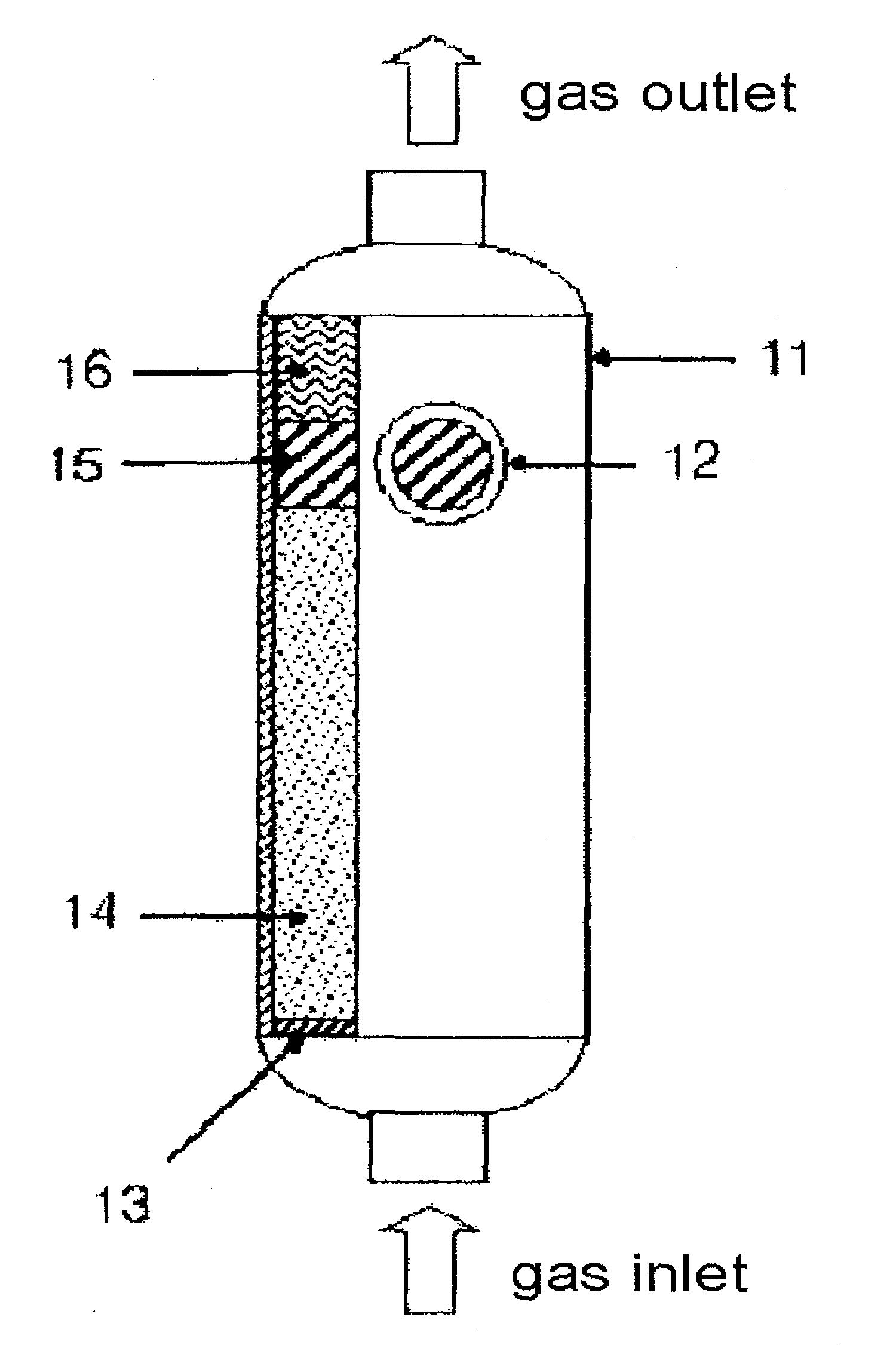
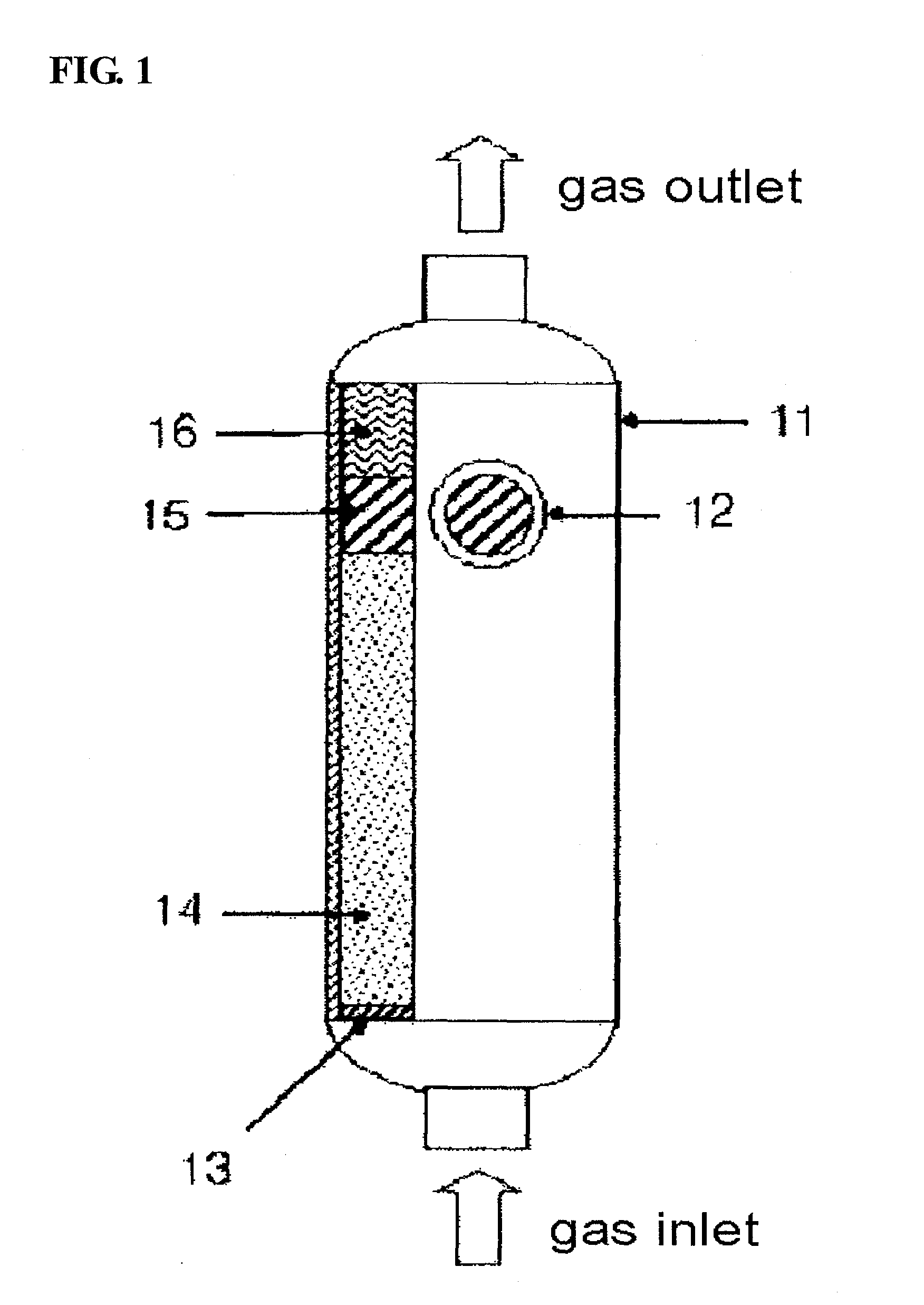
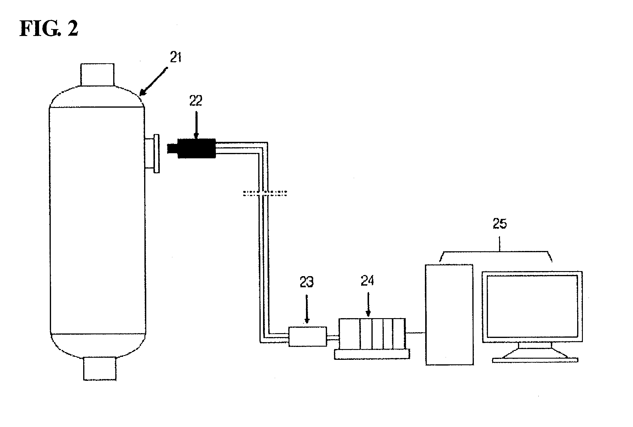

Image

  • Discoloration indicators for checking life span of desulfurization disorbent, and desulfurization reactor and desulfurization system comprising the same
  • Discoloration indicators for checking life span of desulfurization disorbent, and desulfurization reactor and desulfurization system comprising the same
  • Discoloration indicators for checking life span of desulfurization disorbent, and desulfurization reactor and desulfurization system comprising the same

Examples


example 1

[0038]0.66 g of manganese nitrate was completely dissolved in 50 cc of deionized water, thus preparing a supporting solution. The prepared solution was supported on spherical silica gel having a 4˜6 mesh size. The supporting process was conducted using vacuum evaporation. While water was slowly evaporated, manganese nitrate was uniformly supported on the silica gel. Excess water was removed from the catalyst supporting solution at 65˜70° C. for 1 hour. The prepared discoloration indicator was dried at 110° C. for 1 hour, thus removing additional water from the interior of the pores. Consequently, the discoloration indicator containing 1 wt % of manganese was prepared.

example 2

[0039]0.32 g of silver nitrate was completely dissolved in 50 cc of deionized water, thus preparing a supporting solution. The prepared solution was supported on spherical silica gel having a 4˜6 mesh size. Then, subsequent preparation procedures were conducted in the same manner as in Example 1, thus preparing the discoloration indicator containing 1 wt % of silver.

[0040]In order to judge whether the prepared discoloration indicator was discolored due to contact with organic sulfur, 2 cc of the manganese-based discoloration indicator, in which manganese was supported, was loaded into a pyrex tube having an inner diameter of 10 mm. Thereafter, while a mixture gas of TBM and THT, having a concentration of 1 ppm, was allowed to flow at a flow rate of 30 cc per min, the color change before or after discoloration was observed. The same experiment was conducted for the silver-supported discoloration indicator. The results are given in Table 1.

TABLE 1Color Change of Discoloration Indicato...

example 3

[0043]An activated carbon adsorbent A (adsorption performance: 0.63 mol / L) having a 30˜50 mesh size and the manganese-based discoloration indicator of Example 1 were loaded into a pyrex tube having an inner diameter of 10 mm at a volume ratio of 7:3. As such, the total loading height was 5 cm. Into the reactor filled with the adsorbent and the discoloration indicator, a mixture gas in which THT and TBM were mixed at a molar ratio of about 7:3 and the total concentration of a sulfur compound in methane was adjusted to 10 ppm was allowed to flow at a flow rate of 100 cc per min. The optical fiber sensor was mounted to the middle portion of the discoloration indicator, that is, ½ of the total height from the lower surface of the discoloration indicator. After 650 hours of flow of the mixture gas, the lower portion of the discoloration indicator began to be discolored. After an additional period of about 50 hours, the discoloration indicator was discolored to blackish brown to ½ of the ...


PUM

PropertyMeasurementUnit
concentrationaaaaaaaaaa
temperatureaaaaaaaaaa
concentrationaaaaaaaaaa

Abstract

This invention relates to a discoloration indicator for checking the life span of a desulfurization adsorbent, and a desulfurization reactor and a desulfurization system including the same, and specifically, to a discoloration indicator for checking the life span of a desulfurization adsorbent able to effectively adsorb and remove organic sulfur compounds from fossil fuels, including natural gas or LPG containing the organic sulfur compound, and to a desulfurization reactor and a desulfurization system including the same. This invention makes it possible to remove the organic sulfur compound using the desulfurization adsorbent and to check the replacement time of the adsorbent with the naked eye or using an electrical signal, and thus may be applied to the treatment of natural gas or LPG requiring desulfurization, and also to hydrogen generators for home fuel cell generation systems or distributed fuel cell generation systems requiring that devices be simple, or requiring unmanned operation.

Description

TECHNICAL FIELD[0001]The present invention relates to a discoloration indicator for checking the life span of a desulfurization adsorbent, and a desulfurization reactor including the same, and, more particularly, to a discoloration indicator, which enables checking of the replacement time of an adsorbent for removing an organic sulfur compound from natural gas, and to a desulfurization reactor and a desulfurization system including the same.BACKGROUND ART[0002]Conventionally, in natural gas mainly used as fuel, a small amount of an organic sulfur compound, such as t-butylmercaptan (TBM), tetrahydrothiophene (THT), and dimethylsulfide (DMS), is included as an odorant in order to make known the danger occurring upon leakage thereof. At present, natural gas, which is domestically supplied, is known to contain THT and TBM organic sulfur compounds mixed at a ratio of about 7:3, in which the total concentration of the odorant is about 4 ppm (15 mg / m3) (Korean Unexamined Patent Publication...

Claims


Application Information

Patent Timeline
Patent Type & Authority Applications(United States)
IPC IPC(8): G01N1/00G01N21/00G01N33/20B01J8/04
CPCG01N31/229Y02E60/50G01N31/00G01N33/00
Inventor KIM, MYUNG JUNYOON, YOUNG SEEK
Owner SK INNOVATION CO LTD
Why Eureka
Eureka Blog
Learn More