Needle injection catheter

Inactive Publication Date: 2009-12-17
CREED JERETT +3
View PDF38 Cites 52 Cited by
  • Summary
  • Abstract
  • Description
  • Claims
  • Application Information

AI Technical Summary

Benefits of technology

[0049](35) In yet another variant, the needle portions are formed of material selected from the group consisting of metallic material, shape memory metal, duromers, fiber reinforced materials, polymer and polymer material with a highly refractive inde

Problems solved by technology

While much focus has been placed on the particular cell types and mechanisms of action within various tissue types and locations within the heart, very little has been developed with respect to the delivery of cells.
This has proved to have mixed effects in the acute timeframe (less than 10 days) but poor results in the chronic setting.
This visualization is not optimal inside a 3D space particularly given the desire to deliver cells specifically to certain areas of interest.
Manipulating the catheter from

Method used


Image

  • Needle injection catheter
  • Needle injection catheter
  • Needle injection catheter

Examples


Example

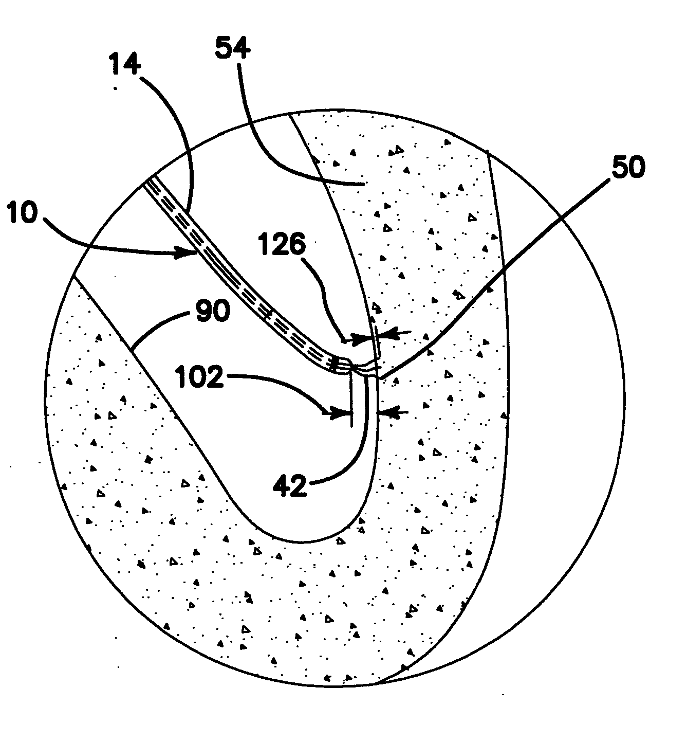
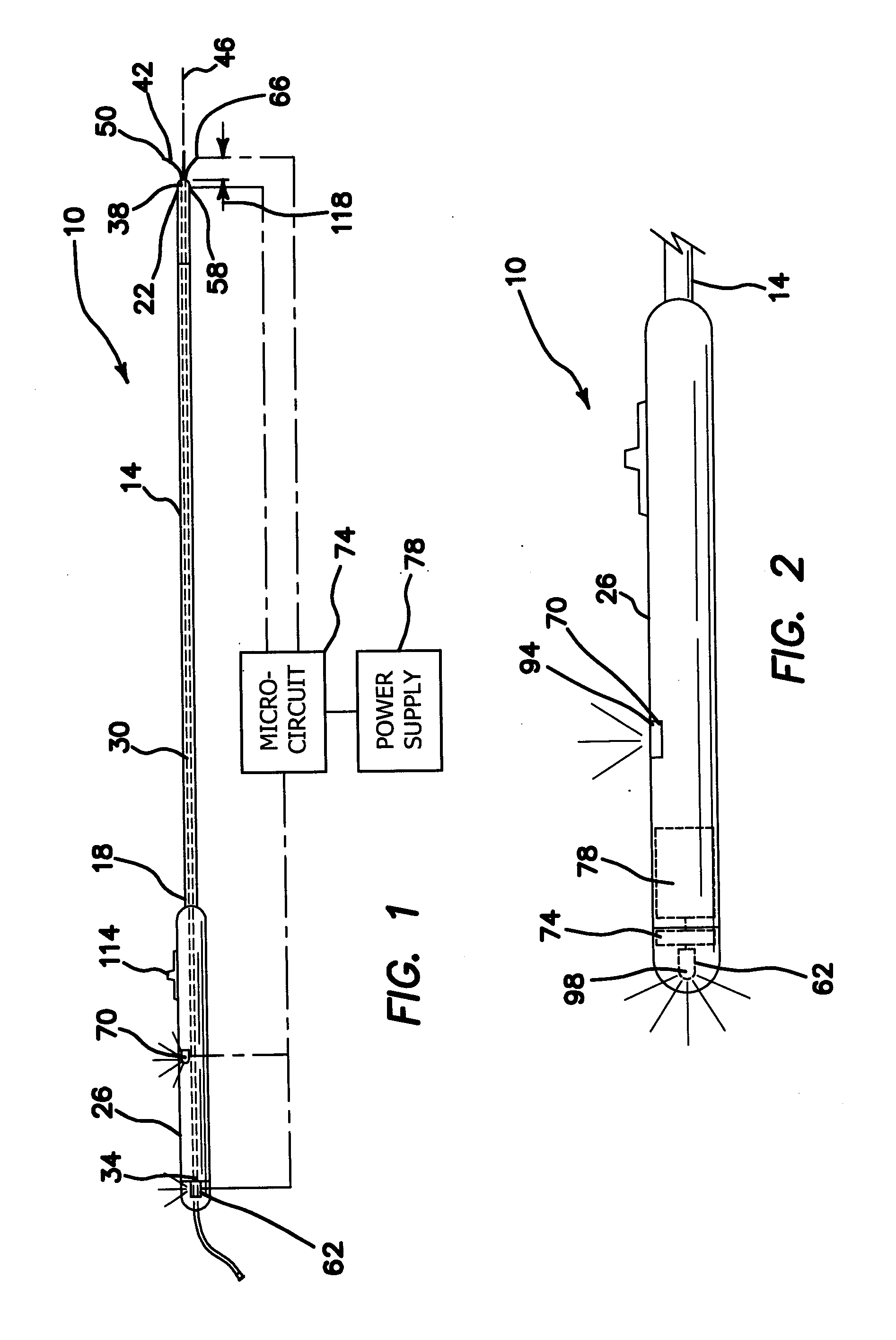
[0142](1) FIG. 1 illustrates a needle injection catheter 10 providing the desired features that may be constructed from the following components. A delivery tube 14 is provided. The delivery tube 14 has a first end 18, a second end 22 and a handle portion 26 adjacent the first end 18. At least one hypotube 30 is provided. The hypotube 30 is sized and shaped to fit slidably within the delivery tube 14. The hypotube has a proximal end 34, a distal end 38 and at least three hollow needle portions 42 connected to and extending outwardly at the distal end 38. The needle portions 42 formed of resilient material, curving outwardly from a central axis 46 of the delivery tube 14 and have ends 50 shaped to penetrate tissue 54 when the hypotube 30 is urged toward the second end 22 of the delivery tube 14. A first sensor 58 is provided. The first sensor 58 is located adjacent the second end 22 of the delivery tube 14 and electrically connected to a first notification device 62 located adjacent ...


PUM


Abstract

The needle injection catheter includes a delivery tube and at least one hypotube that fits slidably within the delivery tube. The hypotube has at least three hollow needle portions extending outwardly at its distal end. The needle portions curve outwardly and have ends shaped to penetrate tissue. At least one reference electrode is located on the delivery tube, spaced from the second end. At least one proximal electrode is located adjacent and spaced from the end of the needle portion. The proximal electrode is electrically connected to a first notification device. A microcircuit is electrically connected to the proximal electrode, the reference electrode and to a power supply. A distal electrode is located adjacent the end of the needle portion and electrically connected to the microcircuit. A tip electrode is located adjacent the second end of the delivery tube and electrically connected to a second notification device and the microcircuit.

Description

RELATED APPLICATION [0001]This application is a Continuation-in-Part of U.S. application Ser. No. 12 / 138,201, filed Jun. 12, 2008 and incorporates by reference the disclosure thereof.FIELD OF INVENTION [0002]This invention relates to the field of stem cell therapies, and more specifically to apparatus and methods for safely injecting cells and therapeutic materials into heart chamber or other organ walls.BACKGROUND OF THE INVENTION [0003]There has been a significant increase in the amount of research and funding in the area of stem cell based therapies for repairing and treating various diseases. More specifically, the number of clinical trials using cell based approaches to treat cardiac related diseases has tripled in the last few years. While much focus has been placed on the particular cell types and mechanisms of action within various tissue types and locations within the heart, very little has been developed with respect to the delivery of cells. Most of the work coming out of...

Claims


Application Information

Patent Timeline
IPC IPC(8): A61B5/042A61B5/055A61B18/18A61B8/14A61M1/00
CPCA61B17/3478A61M2025/0089A61B18/1492A61B19/54A61B2017/00026A61B2017/00035A61B2017/00044A61B2017/00084A61B2017/00092A61B2017/00106A61B2017/00115A61B2017/00221A61B2017/00243A61B2018/1425A61M2025/0086A61B18/1477A61B90/39
Inventor CREED, JERETTPERIN, EMERSONSAUERTEIG, KNUTGRANADA, JUAN
Owner CREED JERETT
Why Eureka
Try Eureka