Balloon Inflation Device

a balloon and inflation device technology, applied in balloon catheters, other medical devices, surgery, etc., can solve the problems of time-consuming and laborious preparation of automatic injection devices for operation, physician may not be able to feel calcium deposit cracking, and physician cannot typically feel the

Active Publication Date: 2009-12-17
ACIST MEDICAL SYST
View PDF76 Cites 53 Cited by
  • Summary
  • Abstract
  • Description
  • Claims
  • Application Information

AI Technical Summary

Benefits of technology

[0007]It would be therefore advantageous to use a balloon inflation device that at least partially automates the priming procedure, according to one embodiment. The balloon inflation device may be a stand-alone device, or it may

Problems solved by technology

Preparing the automatic injection device for operation can be a time-consuming process.
Thus, the physician cannot typically feel the effect that the balloon may be having on the wall of the vessel that it is stretching against.
For example, the physician may not be able to feel a calcium deposit cracking.
The special syringes typically include a pressure gauge, but the gauge is often located on the syringe i

Method used


Image

  • Balloon Inflation Device
  • Balloon Inflation Device
  • Balloon Inflation Device

Examples


Embodiment Construction

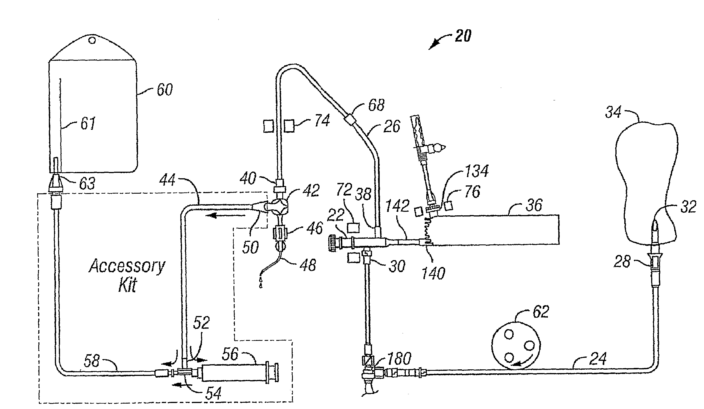
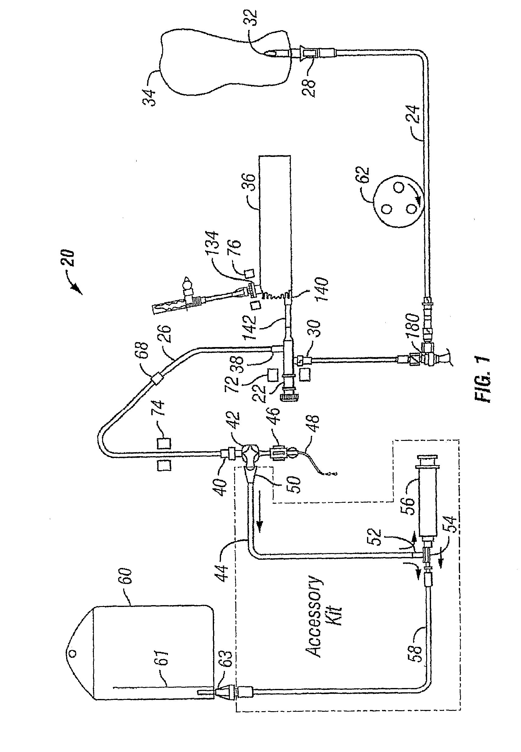
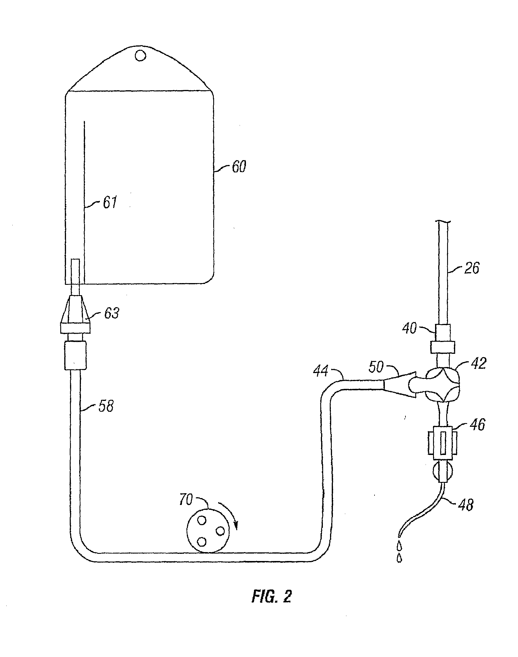
[0028]Referring now to the Figures, and first to FIG. 1, there is shown a fluid network 20 comprising a disposable patient manifold 22 connected to a saline line 24 and an output line 26. The saline line 24 has a first end 28 and a second end 30. The first end 28 is connected to a bag connector 32, useable to establish fluid communication between the line 24 and a saline bag 34.

[0029]The patient manifold 22 is also connected to a syringe 36 of an automatic injection device (not shown) for receiving the fluid ejected therefrom. The patient manifold 22 is thus useable to selectably connect the output line 26 with either the saline line 24 or the syringe 36. The patient manifold 22 may be any device capable of selectively directing flow between at least three ports, such as a three-way check valve, a manual or automatic three-way stopcock, a motor operated valve, or a collection of check valves operably disposed within the appropriate lines to effect the desired flow directions. Prefer...


PUM


Abstract

One embodiment provides a method implemented by a powered inflation device to prepare a balloon catheter for use during a medical procedure. In this embodiment, the method includes drawing an amount of medical fluid from a fluid reservoir into the inflation device during a first motorized operation of the inflation device, removing an amount of air from the balloon catheter during a second motorized operation of the inflation device, and injecting the amount of medical fluid from the inflation device into the balloon catheter during a third motorized operation of the inflation device to inflate a balloon located at a distal end of the balloon catheter The powered inflation device may be a stand-alone device in one embodiment. In one embodiment, the powered inflation device is coupled to an angiographic injector system. When it is coupled to an angiographic injector system, the balloon inflation device and the injector system may be controlled by a common control panel, or console, in one embodiment.

Description

TECHNICAL FIELD[0001]The present application relates generally to the use of injection devices in medical systems, and more specifically to the use of balloon inflation devices.BACKGROUND OF THE INVENTION[0002]Automatic injection devices, such as Applicant's device described in U.S. Pat. No. 6,099,502, are used to deliver fluids such as saline and contrast agents through a catheter to a patient. The devices typically include a motor-driven linear actuator that forces a plunger through a syringe, thereby creating a desired fluid flow into the patient. For sanitation purposes, the syringe and all associated tubing between the patient and the syringe may be disposable.[0003]Preparing the automatic injection device for operation can be a time-consuming process. Various tubes may need to be connected together and to the device. The operator preparing the injection device for operation must often be careful to ensure that the connections arc tight and that none of the tubes arc pinched or...

Claims


Application Information

Patent Timeline
IPC IPC(8): A61M31/00A61M29/00A61F2/958
CPCA61M25/1018A61M2025/1022A61M2025/102A61M25/10188A61M25/10182A61M25/10185
Inventor KIM, ROBERTLIU, JIYANMCPEAK, THOMASMOHIUDDIN, KHADERMOON, JONOFTEDAHL, RICHARD A.SCHWARTZ, NORMANTOEWS, GLENNWILSON, ROBERT F.
Owner ACIST MEDICAL SYST
Why Eureka
Try Eureka