
Methods and systems for manufacturing modified asphalts

a technology of modified asphalt and manufacturing methods, applied in the direction of chemical/physical processes, building components, process and machine control, etc., can solve the problems of large amount of power drawn by the in-line mixer, inability to accurately measure the impact of asphalt, etc., to achieve high viscosity of asphalt, reduce the effect of affecting the effect of agitation and high efficiency

Inactive Publication Date: 2009-12-17
FLEX PROD LLC
View PDF59 Cites 25 Cited by
  • Summary
  • Abstract
  • Description
  • Claims
  • Application Information

AI Technical Summary

Benefits of technology

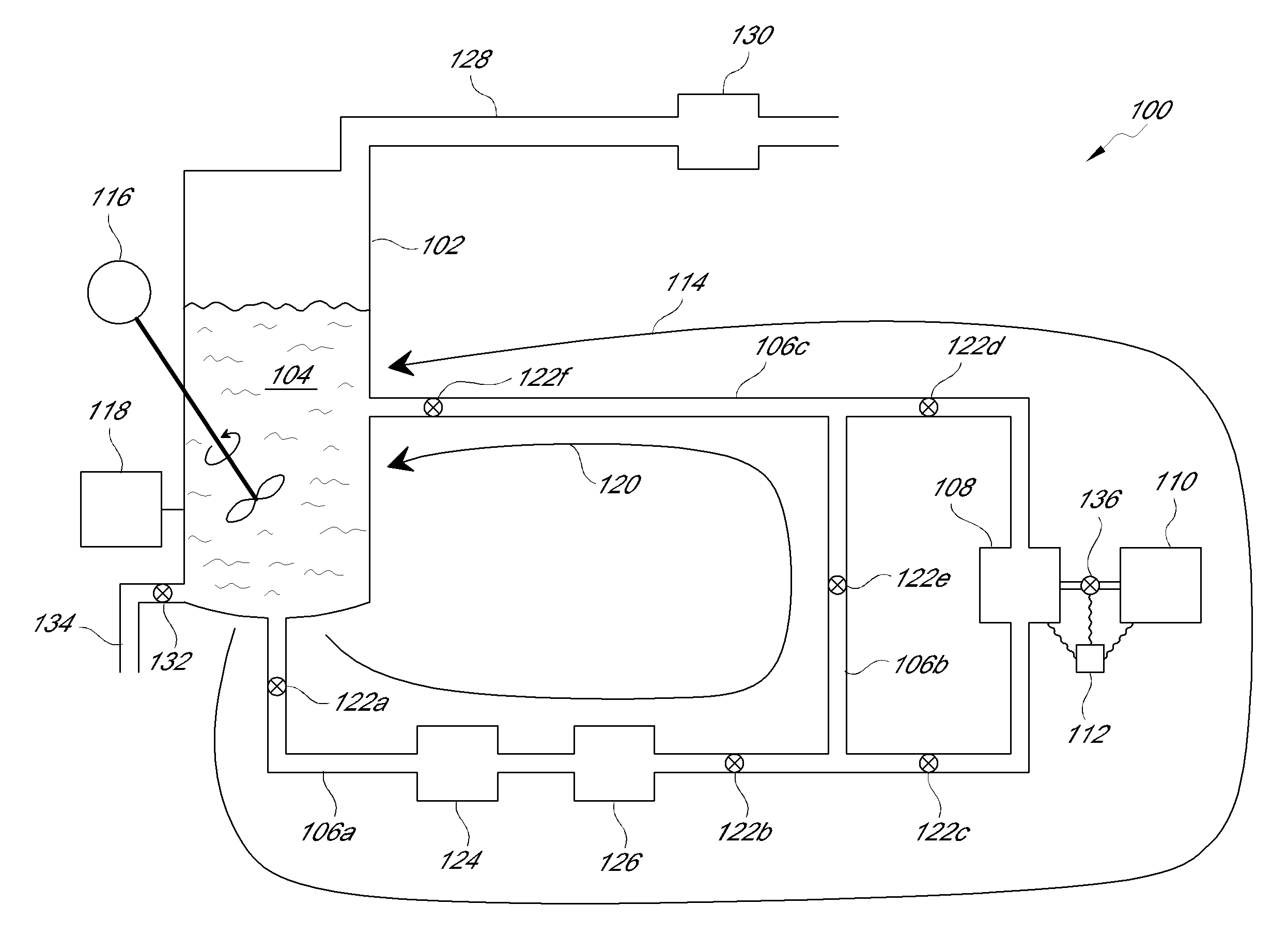
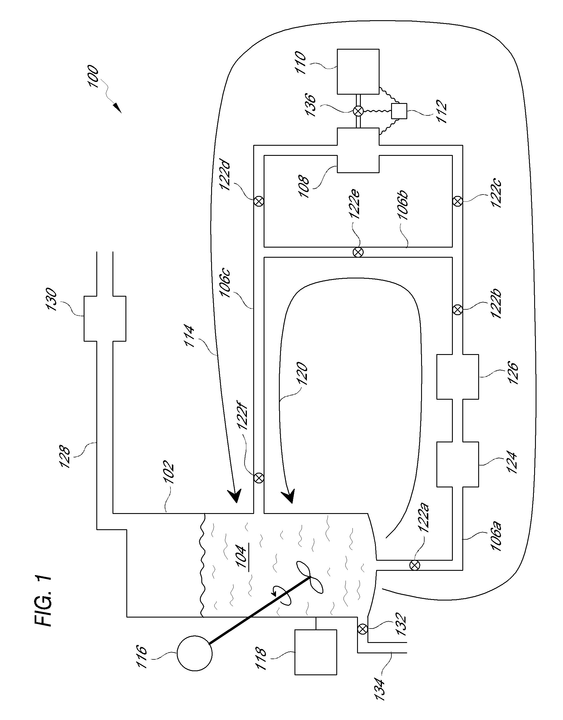
[0007]Preferred embodiments provide improvements to the asphalt modification methods and systems described in U.S. Pat. No. 7,374,659. In particular, preferred embodiments provide systems and methods for efficiently manufacturing modified asphalt using an in-line mixer equipped with a rotor-stator mixing tool. The rotor-stator mixing tool applies high levels of shear to the base asphalt, and contains openings that are configured to allow an oxygen-containing gas to be blown through the base asphalt while flowing the base asphalt through the in-line mixer at an elevated temperature to form modified asphalt. In the past, the use of in-line mixers for agitating asphalt on a large scale had been considered relatively inefficient because it was believed that relatively large (and expensive) in-line mixers drawing undesirably large amounts of power would be needed because of the relatively high viscosity of the asphalt, even at elevated temperatures. Surprisingly, it has been found that the flow rate of the oxygen-containing gas through the in-line mixer (and thus through the openings in the rotor-stator mixing tool) significantly affects the power drawn by the in-line mixer during the agitating of the base asphalt. It has also been found that the flow rate of the base asphalt through the in-line mixer affects the power drawn by the in-liner mixer, and that efficiency can be improved by controlling the temperature of the modified asphalt during production by selection of the pumping rate for the base asphalt through the in-line mixer.
[0010]In an embodiment, the base asphalt flow rate, the high gas flow rate, the high shear rate, the elevated temperature and the treatment time are all selected to substantially improve both the rutting resistance and the fatigue resistance of the modified asphalt as compared to the base asphalt. In an embodiment, the base asphalt flow rate is further selected to control the amount of power drawn by the in-line mixer during the agitating of the base asphalt, the amount of power being in the range of about 60% to about 95% of the maximum power rating. In an embodiment, the base asphalt flow rate is further selected to provide a temperature of the modified asphalt in the range of about 380° F. to about 470° F. In an embodiment, the high gas flow rate is further selected to control the amount of power drawn by the in-line mixer during the agitating of the base asphalt, the amount of power being in the range of about 60% to about 95% of the maximum power rating. In an embodiment, the agitating of the base asphalt at the high shear rate using the rotor-stator mixing tool comprises recirculating at least a portion of the base asphalt through the in-line mixer.

Problems solved by technology

In the past, the use of in-line mixers for agitating asphalt on a large scale had been considered relatively inefficient because it was believed that relatively large (and expensive) in-line mixers drawing undesirably large amounts of power would be needed because of the relatively high viscosity of the asphalt, even at elevated temperatures.
Surprisingly, it has been found that the flow rate of the oxygen-containing gas through the in-line mixer (and thus through the openings in the rotor-stator mixing tool) significantly affects the power drawn by the in-line mixer during the agitating of the base asphalt.
Such selections of pumping rate and gas flow rate for the oxygen-containing gas are less than would otherwise be considered optimal because in many cases the asphalt is insufficiently oxidized by a single pass through the in-line mixer, and often the desired level of modification is achieved after recycling the asphalt through the in-line mixer.
However, in terms of overall manufacturing efficiency, it has been found that the negative impact on throughput resulting from such recycling is more than offset by energy cost savings obtained by operating the in-line mixer in such a way that it draws an amount of power that is in the range of about 60% to about 95% of the maximum power rating of the in-line mixer.

Method used


Image

  • Methods and systems for manufacturing modified asphalts
  • Methods and systems for manufacturing modified asphalts
  • Methods and systems for manufacturing modified asphalts

Examples


example 1

[0052]A batch of Valero PG 58-22 asphalt was obtained commercially and modified in accordance with the following procedure. The asphalt was subjected to a standard preliminary procedure known as the rolling thin film oven (“RTFO”) procedure, which is well known in the art. The RTFO procedure simulates the conditions under which asphalt is processed in a hot-mix plant.

[0053]Twelve tons of the base asphalt (Valero PG 58-22 after application of RTFO procedure) was loaded into the container 102 at a loading temperature in the range of about 300° F. to about 350° F. Circulation of the base asphalt through the heated flow line 106b in the bypass loop 120 began as the material was heated to a temperature in the range of about 380° F. to about 400° F. Once heated, high shear agitation of the base asphalt was initiated by opening the valves 122d and 136, partly opening the valve 122c and allowing the base asphalt to flow through the in-line mixer 108. A portion of the base asphalt in the byp...

example 2

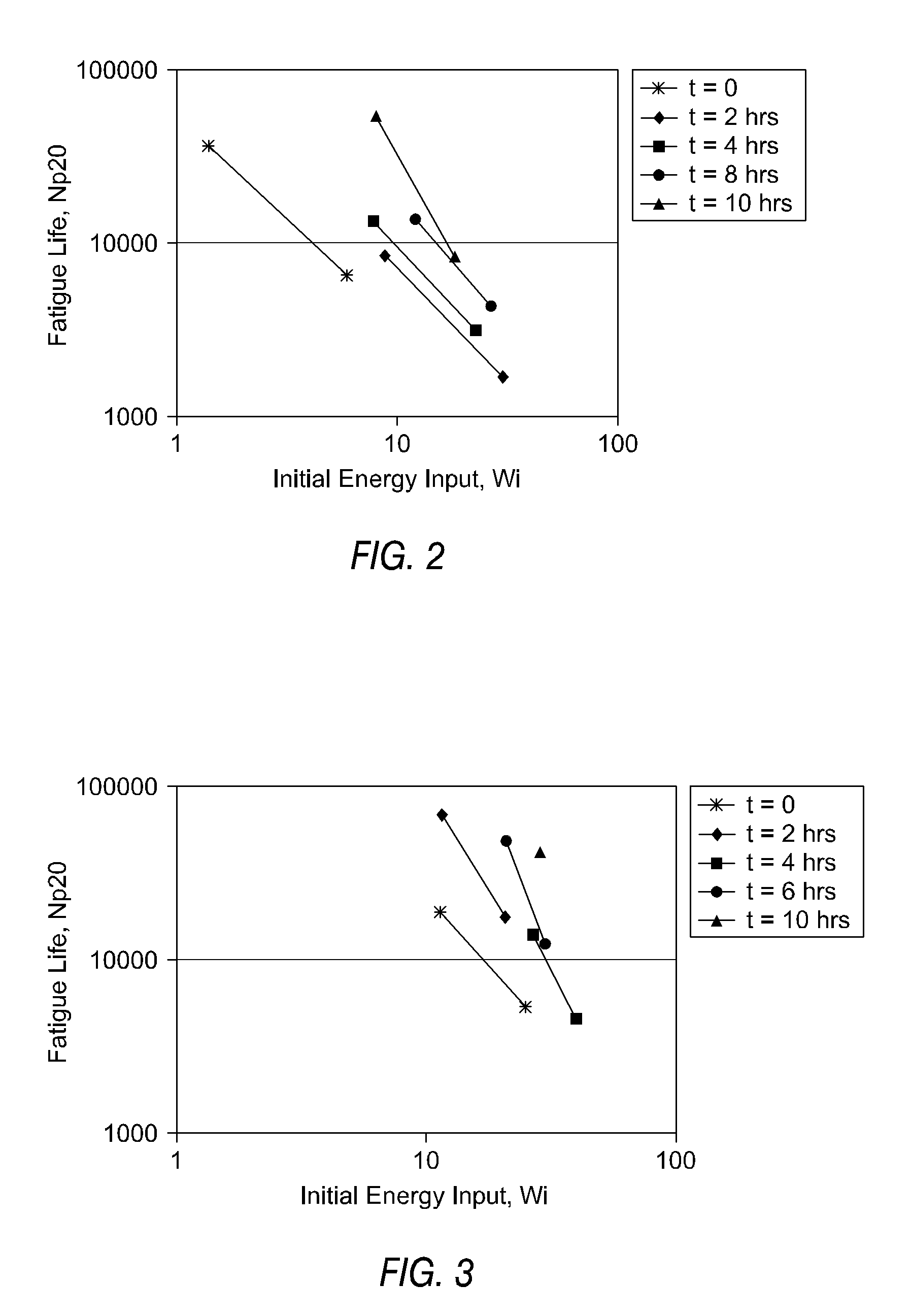
[0057]A batch of Valero PG 58-22 asphalt was obtained commercially and modified in accordance with the procedure described in Example 1. However, this batch of asphalt was subjected to a different preliminary procedure known as the pressure aging vessel (“PAV”) procedure, which is well known in the art. The PAV procedure simulates field aging. As in Example 1, samples were taken at various modification times, although the sample taken after 10 hours of modification was only tested at one stress level. As shown in FIG. 3, the fatigue life of the samples is improved upon modification of the asphalt as described herein. The fatigue resistance is improved in terms of both the life duration of the material (as indicated by increased values of Np20) and the amount of energy (as indicated by increased values of Wi) that it can absorb.

example 3

[0058]A batch of AR-8000 asphalt was obtained commercially from San Joaquin Refining and modified in accordance with the procedure described in Example 1, with the exception that no preliminary RTFO procedure was applied.

[0059]Samples were removed after 0 hours (starting material), 2.25 hours, 5.25 hours, 6.25 hours, 7.75 hours, and 8.5 hours, respectively. The modified asphalts were tested for rutting resistance following the MSCR procedure by applying a load for 1 second and removing it for 9 seconds. The loading sequence was applied for 10 cycles at 100 Pa followed by 10 cycles at 3200 Pa. FIGS. 4 and 5 show the non-recoverable creep compliance (Jnr) for the 100 Pa test and the 3200 Pa test, respectively. Data points were taken at about 64° C. and at about 70° C. for each sample. As seen in FIG. 4 and FIG. 5, the Jnr values steadily decreased with increased processing times, indicating increased stiffness and greater rutting resistance. The margin of improvement is significant an...


PUM

PropertyMeasurementUnit
Temperatureaaaaaaaaaa

Abstract

Methods and systems for efficiently manufacturing modified asphalt materials include agitating a base asphalt at a high shear rate using an in-line mixer equipped with a rotor-stator mixing tool while simultaneously exposing the asphalt to oxygen by blowing an oxygen-containing gas at a high gas flow rate through openings in the rotor-stator mixing tool and heating the asphalt at an elevated temperature.

Description

CROSS-REFERENCE TO RELATED APPLICATIONS[0001]This application is related to, and claims the benefit of, U.S. Provisional Application No. 61 / 061,316, filed Jun. 13, 2008, which is hereby incorporated by reference in its entirety for all purposes.BACKGROUND OF THE INVENTION[0002]1. Field of the Invention[0003]This invention generally relates to systems and methods for efficiently manufacturing modified asphalt materials.[0004]2. Description of the Related Art[0005]Conventional air-blowing of asphalt materials involves passing an oxidizing gas through the asphalt in a molten condition. In general, the effect of such conventional air-blowing is to partially oxidize the asphalt, resulting in decreased penetration and increased viscosity and softening point. However, for paving applications, such conventional air-blowing generally has a negative effect on the fatigue resistance and the low temperature properties.[0006]U.S. Pat. No. 7,374,659, issued May 20, 2008, describes methods for mak...

Claims


Application Information

Patent Timeline
IPC IPC(8): C08L95/00B28C5/38G05D11/02B01F35/60G05D7/06
CPCB01F3/04531C10C3/04B01F7/0075B01F5/10B01F23/233B01F25/50B01F27/27
Inventor BURRIS, MICHAEL V.BURRIS, BRYAN B.AJIDEH, HOSSEINCLAYTON, ANDREW
Owner FLEX PROD LLC
Learn More