Drying device and sanitary washing apparatus equipped with the same

a technology of sanitary washing apparatus and drying device, which is applied in the direction of water installation, construction, domestic applications, etc., can solve the problems of increasing increasing the cost of the toilet, and increasing the noise of vibration, so as to achieve the effect of enlarging the size of the drying device and efficiently drying in a short tim

Inactive Publication Date: 2009-12-24
PANASONIC CORP
View PDF4 Cites 46 Cited by
  • Summary
  • Abstract
  • Description
  • Claims
  • Application Information

AI Technical Summary

Benefits of technology

[0021]For example, this first moving device moves in an advancing / retracting direction of the air blowing portion, and the second moving device deflects the blowing direction of the jet.
[0022]According to the invention, the waterdrops attached to the surface to be dried in a wide range can be blown off without being spread even with a small jet of air, so that the surface to be dried can be dried efficiently in a short time without enlarging the size of the drying device.

Problems solved by technology

In addition, if the capacity of the air compressor 13 is made large, not only does the vibration noise become large, but also it constitutes a cause of increased cost.
Furthermore, if the high-pressure air accumulator is separated from the air compressor and is installed outside the main body case, it becomes conspicuous, so that the appearance of the toilet becomes aggravated.
With this method, however, the area of air blown also becomes small, so that there has been a problem in that it becomes impossible to sufficiently remove the waterdrops on the surface to be washed which is wet in a wide range, and there has been a problem in practical application.
In addition, the waterdrops which were not peeled off the surface to be washed by a jet of air from a fixed direction undesirably move to a stagnant portion of the jet of air and remain as attached to the surface to be washed.
Further, there has been an additional problem in that the waterdrops are spread to the periphery by the jet of air, enlarging the wet area.
However, although it is not clear from the description of the above-described configuration, it appears that this device deflects the blowing direction of air three-dimensionally.
However, there has been a problem in that in a case where actual drying operation is performed by deflecting the blowing direction of the air nozzle on the basis of this description, if attention is focused on the relationship between the angle at which the blown air is applied and the surface to be dried, the waterdrops at the peripheral portion among the waterdrops after washing are further blown away and spread toward the surrounding parts.

Method used


Image

  • Drying device and sanitary washing apparatus equipped with the same
  • Drying device and sanitary washing apparatus equipped with the same
  • Drying device and sanitary washing apparatus equipped with the same

Examples


first embodiment

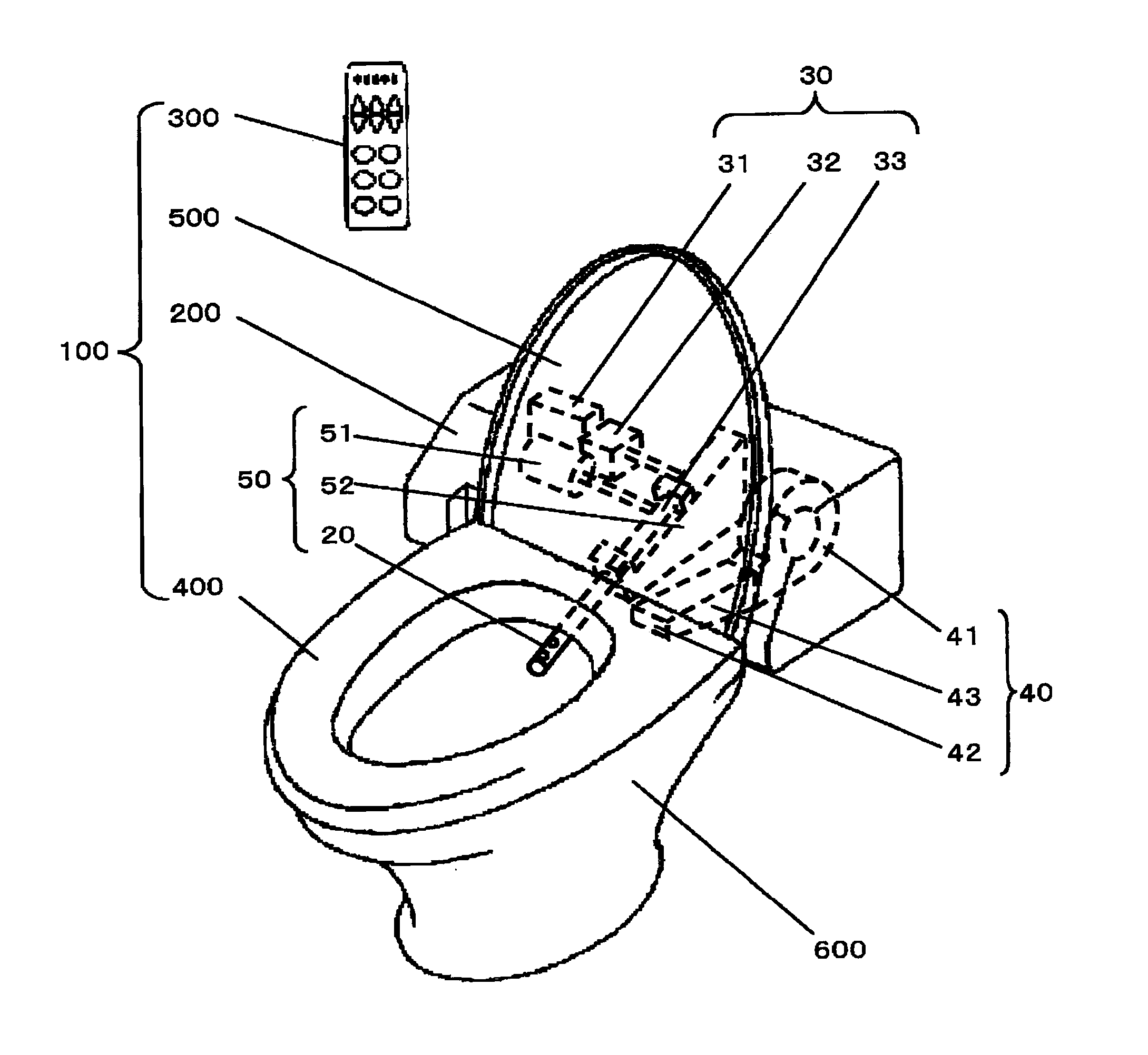
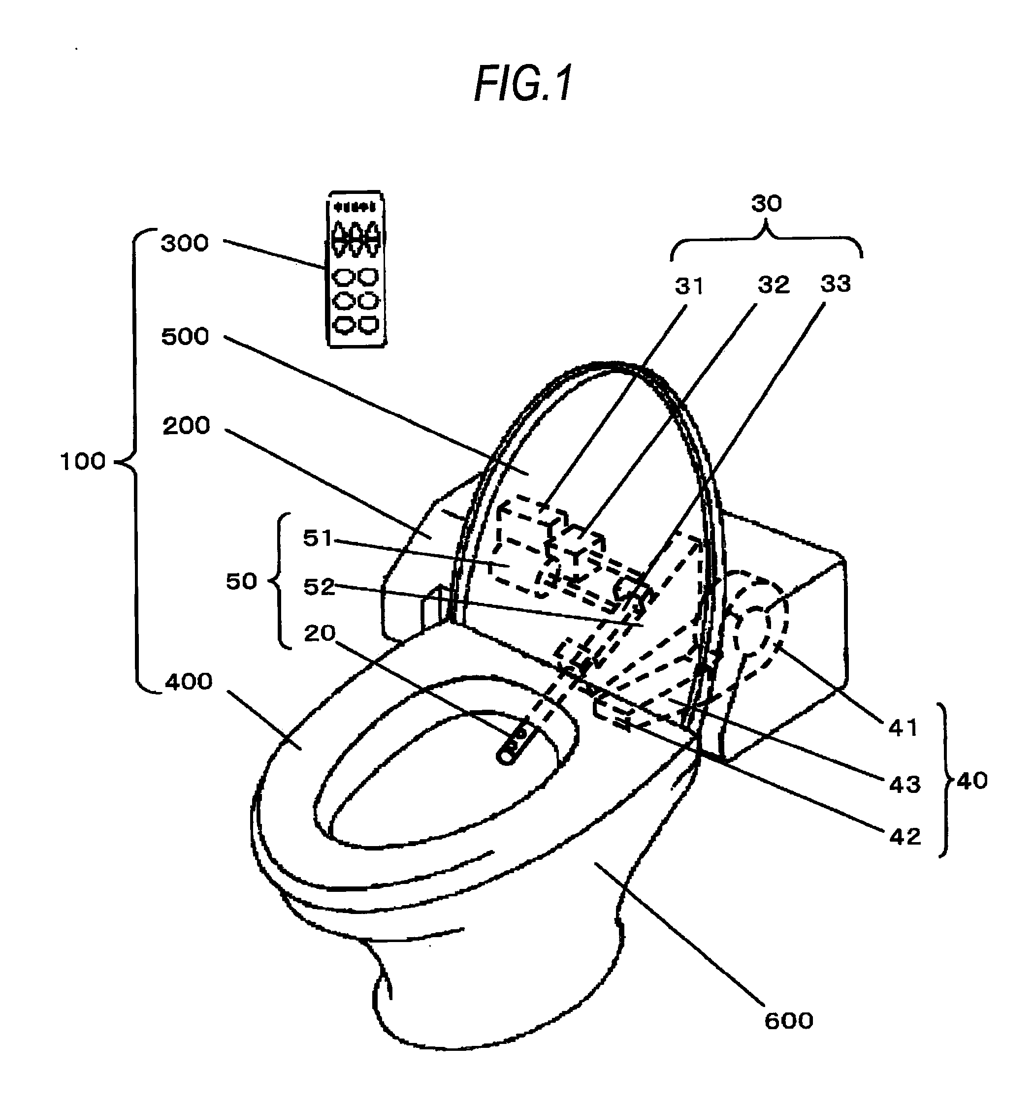
[0145]FIG. 1 is a perspective view illustrating a state in which a sanitary washing apparatus in accordance with an embodiment of the invention is mounted on a toilet bowl.

[0146]As shown in FIG. 1, a sanitary washing apparatus 100 in accordance with an embodiment of the invention is mounted on a toilet bowl 600.

[0147]The sanitary washing apparatus 100 is comprised of a main body 200, a remote control device 300, a toilet seat 400, and a cover 500.

[0148]The toilet seat 400 and the cover 500 are openably attached to the main body 200. Further, the main body 200 is provided with a drying device 50 including a drying nozzle 20 which is an air blowing portion, a washing water spraying unit 30 for spraying washing water, and a heating unit 40, and a controller is incorporated therein. The controller in the main body 200 controls the drying device 50, the heating unit 40, and the washing water spraying unit 30 on the basis of a signal transmitted by the remote control device 300, as will b...

second embodiment

[0208]Next, a description will be given of a sanitary washing apparatus in accordance with a second embodiment of the invention.

[0209]The sanitary washing apparatus in accordance with the second embodiment differs from the sanitary washing apparatus in accordance with the first embodiment in the following aspects.

[0210]FIG. 10 is a partial perspective view of the drying nozzle of the drying device and the swinging device in the sanitary washing apparatus in accordance with the second embodiment of the invention.

[0211]A swinging device 80 shown in FIG. 10 includes a rotating shaft portion 83 connected integrally to a proximal portion 82 of a drying nozzle 81 which is an air blowing portion, a slider 85 for supporting the rotating shaft portion 83 rotatably about an axis 84 of the rotating shaft portion 83, a left-right driving motor 86 for rotating the rotating shaft portion 83, and a gear A 87 and a gear B 88 for transmitting the torque of the left-right driving motor 86 to the rota...

third embodiment

[0216]Next, a description will be given of a sanitary washing apparatus in accordance with a third embodiment of the invention.

[0217]The sanitary washing apparatus in accordance with the third embodiment differs from the sanitary washing apparatus in accordance with the first embodiment in the following aspects.

[0218]FIG. 11 is a timing chart of the controlling operation in “posterior washing” and “drying” operation by the controller of the sanitary washing apparatus. FIG. 12 is a schematic diagram illustrating a moving pattern of the abutment area of the jet of air with respect to the surface to be dried in the state of “drying” operation.

[0219]In the third embodiment, in the meantime from T7 till T13 in FIG. 11, the abutment area E of the jet of air is moved over the outer peripheral portion of the surface F to be dried shown in FIG. 12, sequentially in the order of backward m1, leftward m2, forward m3, rightward m4, and backward m5, and its drive range is thus made to gradually a...


PUM


Abstract

A drying device in accordance with the invention is characterized by including: an air blowing portion for blowing pressurized air so as to dry a surface to be dried by a jet of pressurized air whose abutment area to the surface to be dried is narrower than the surface to be dried; and a moving unit for moving the air blowing portion while the jet is being blown such that the jet blown from the air blowing portion sequentially sweeps a substantially entire surface of the surface to be dried, wherein the moving unit includes a first moving device for moving the air blowing portion in a state in which a blowing direction of the jet is being maintained so as to form a predetermined angle with respect to a moving direction of the air blowing portion and a second moving device for moving the air blowing portion in a direction different from that of the moving direction.For example, this first moving device moves in an advancing / retracting direction of the air blowing portion, and the second moving device deflects the blowing direction of the jet.

Description

TECHNICAL FIELD[0001]The present invention relates to a drying device for drying a wet surface by blowing air and a sanitary washing apparatus equipped with the same.BACKGROUND ART[0002]In a sanitary washing apparatus for washing the private parts of the human body, various functions have been devised to realize washing which corresponds to users' preferences. The user performs washing of the private parts by using the sanitary washing apparatus using the various functions, and effected removal of drops of water attached to the private parts with paper such as toilet paper. In recent years, however, a drying device has been proposed as a substitute for the paper such as toilet paper (e.g., refer to patent document 1). FIG. 21 is a schematic plan view illustrating an example of a conventional sanitary washing apparatus equipped with a drying device. FIG. 22 is a schematic side cross-sectional view of this conventional sanitary washing apparatus.[0003]As shown in FIGS. 21 and 22, the ...

Claims


Application Information

Patent Timeline
Patent Type & Authority Applications(United States)
IPC IPC(8): A47K17/00
CPCE03D9/08A47K10/48
Inventor KUNIMOTO, KEIJIROUOHNO, HIDEKISHIRAI, SHIGERUSHIMADA, YOSHIHARU
Owner PANASONIC CORP
Why Eureka
Try Eureka