

Hinge with electrical wiring
- Summary
- Abstract
- Description
- Claims
- Application Information
AI Technical Summary
Benefits of technology
Problems solved by technology
Method used
Image

Examples
Embodiment Construction
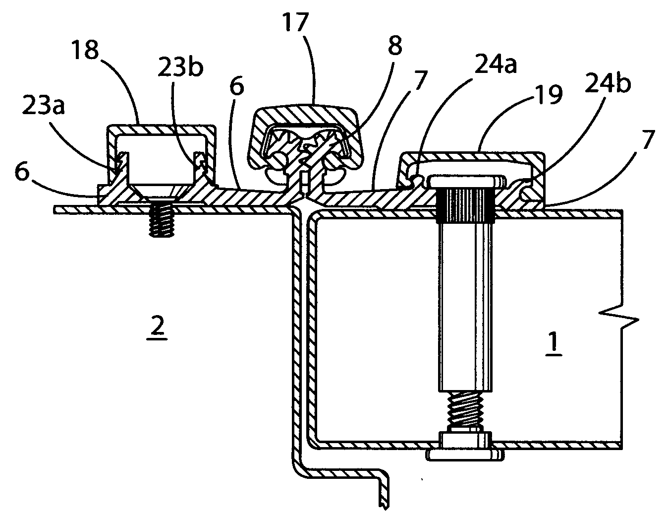
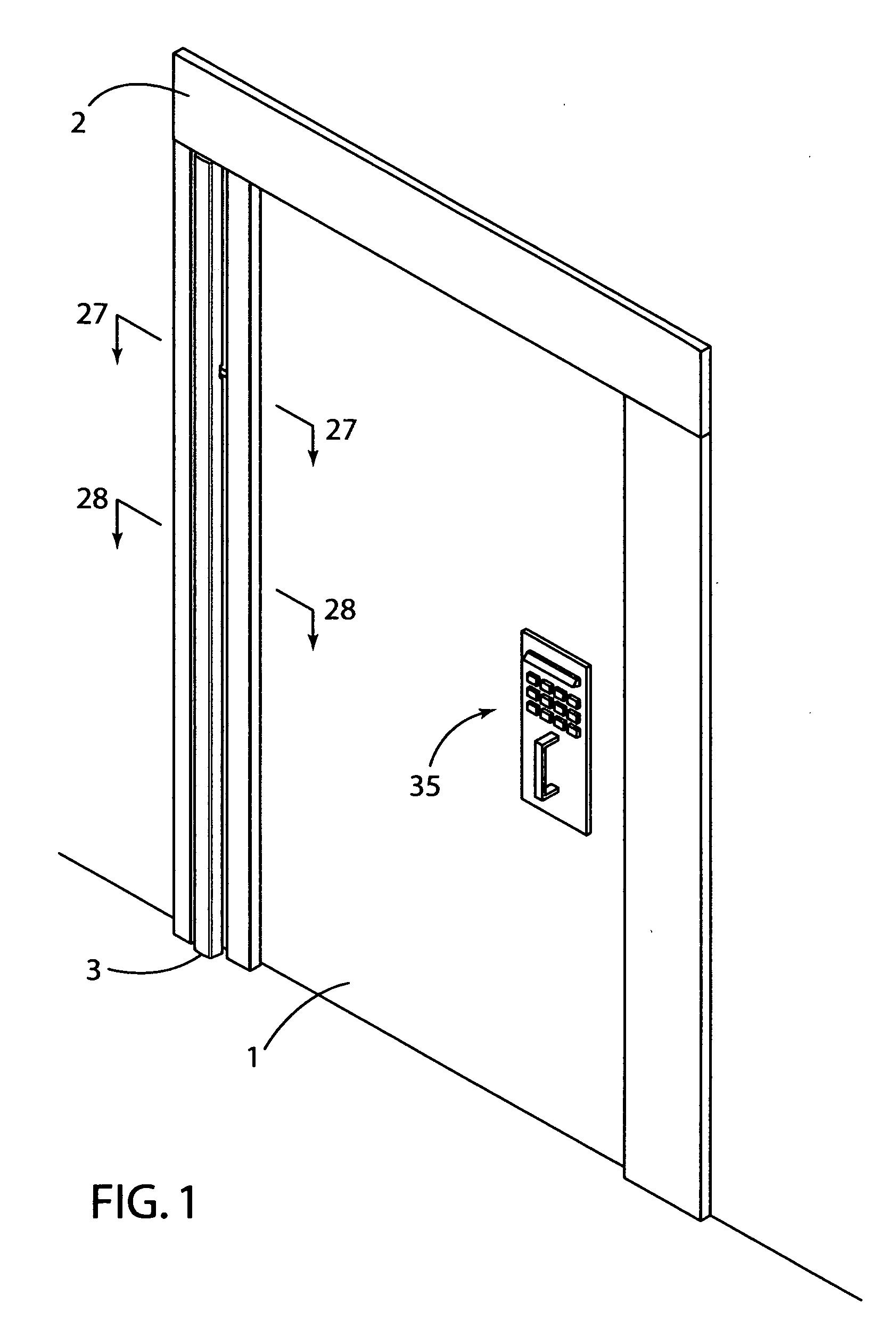
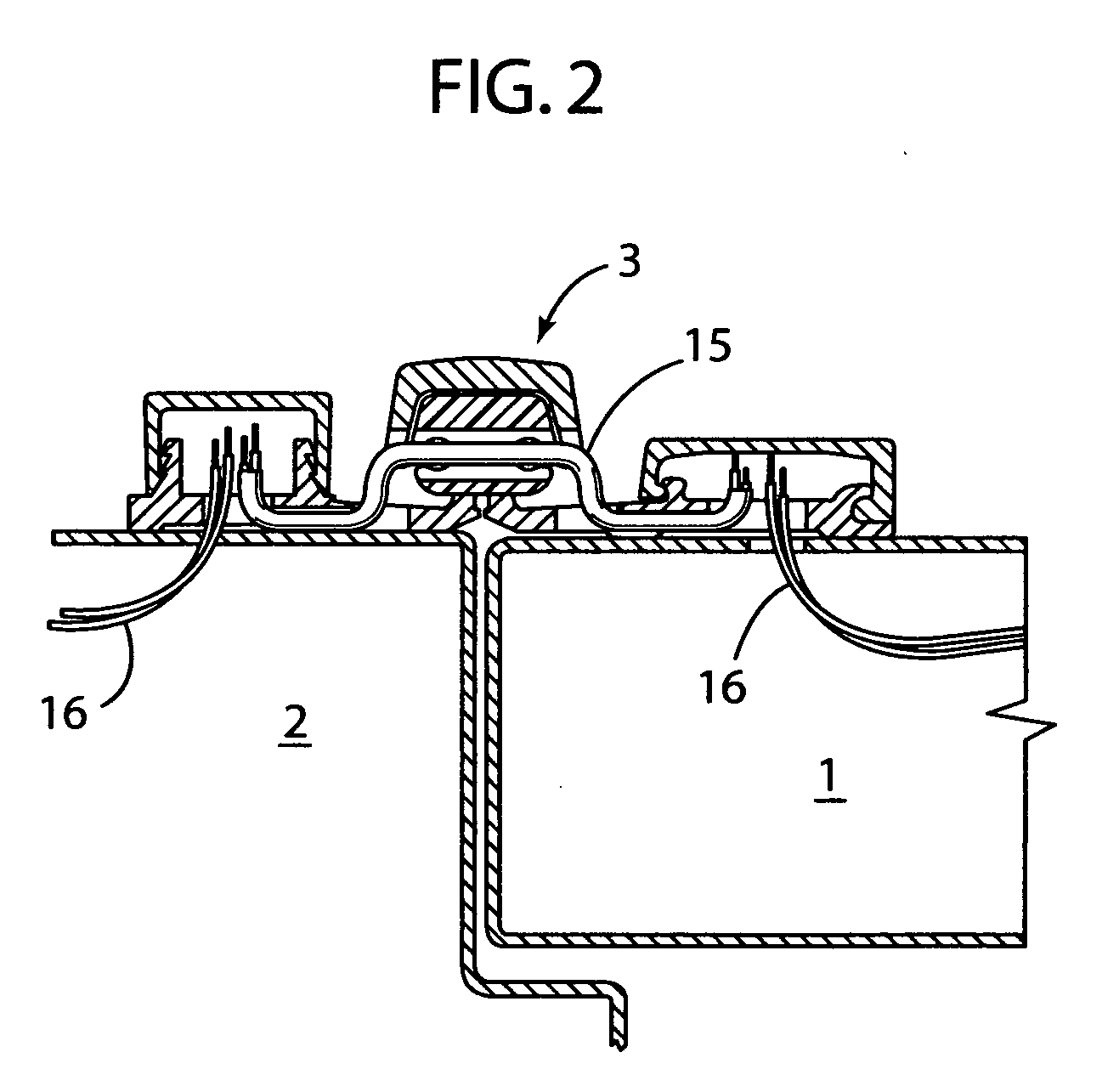
[0054]The preferred embodiments of the present invention consist of the following components as more clearly shown in FIGS. 1-13:[0055](1) A full surface mount type geared aluminum or equivalent continuous door hinge 3 of any length.[0056](2) From one to 15 strands of 22 gauge flexible wire 16 in lengths of from 5 to 36 inches.[0057](3) From at least 1 to about 3 modified thrust bearings 9.[0058](4) PVC or equivalent flexible tubing 15 in a diameter suitable to pass through a hole 10 in the modified thrust bearings 9.[0059](5) A gear cap 17 to cover the meshed gears 8 and bearings 9,31 and two covers 18,19 to cover the machined holes 11,13,25,26 in the plates 6,7 of the leaves 4,5.[0060]The essential equipment required to convert an ordinary geared continuous full surface hinge into the above embodiments include:[0061](1) A machine tool capable of repeatedly machining precision holes, channels and the like.[0062](2) Tooling capable of machining metals.[0063](3) Work holding fixtures...
PUM
 Abstract
Description
Claims
Application Information