High density cotton picker bar and spindle assembly therefor

a technology which is applied in the field of cotton picker bar and spindle assembly therefor, can solve the problems of limited density of spindle on the picker bar and continuing difficulty, and achieve the effect of improving productivity and facilitating closer vertical spacing of the spindl

Inactive Publication Date: 2009-12-24
DEERE & CO
View PDF8 Cites 8 Cited by
  • Summary
  • Abstract
  • Description
  • Claims
  • Application Information

AI Technical Summary

Benefits of technology

[0004]A picker bar includes spindles which are nonaligned in the vertical direction to define two or more offset sets of spindles on the bar and facilitate closer vertical spacing of the spindles. The number of spindles per unit length of the spindle bar is thereby increased to provide more spindles in the pick zone for increased productivity.
[0005]In one embodiment of the invention, two spindles of a twin spindle assembly are driven by a central gear which, in turn, is driven by bevel gear mounted to the picker bar driveshaft. The two spindles are mounted at an angle to the vertical plane of the bar to define two vertical planes of spindles. The reduced number of drive gears on the drive shaft allows an increased total number of spindles on each picker bar and provides an increased number of horizontal spindle planes. The spindle plane spacing for the pair of spindles may be different than the spacing between planes for adjacent spindles in adjacent pairs, and doffing with such spacing is achieved with a doffer column having two different sizes or spacing of doffer pads.
[0006]Various drives, including a crossed helical drive, double shaft drive, spiral bevel gear drive, or a hypoid gear set can be utilized to achieve more than one vertical plane of spindles on a spindle bar. Two or more picker spindle planes lying on either side of the central axis of the bar allows the horizontal distance between the two closest pick zones to be reduced. With helical or hypoid type gear drives, the spindle planes may be offset from a parallel relationship. For example, by slightly angling the planes relative to one another, horizontal spindle distribution in the pick zone can be improved.

Problems solved by technology

The spacing between the spindle planes and thus the density of the spindles on the picker bar is limited by the spindle support and spindle drive arrangement.
Therefore, increasing the spindle density for increased drum productivity while maintaining the reliability of the spindle, spindle bar and spindle drive has heretofore been a continuing source of difficulty.

Method used


Image

  • High density cotton picker bar and spindle assembly therefor
  • High density cotton picker bar and spindle assembly therefor
  • High density cotton picker bar and spindle assembly therefor

Examples


Embodiment Construction

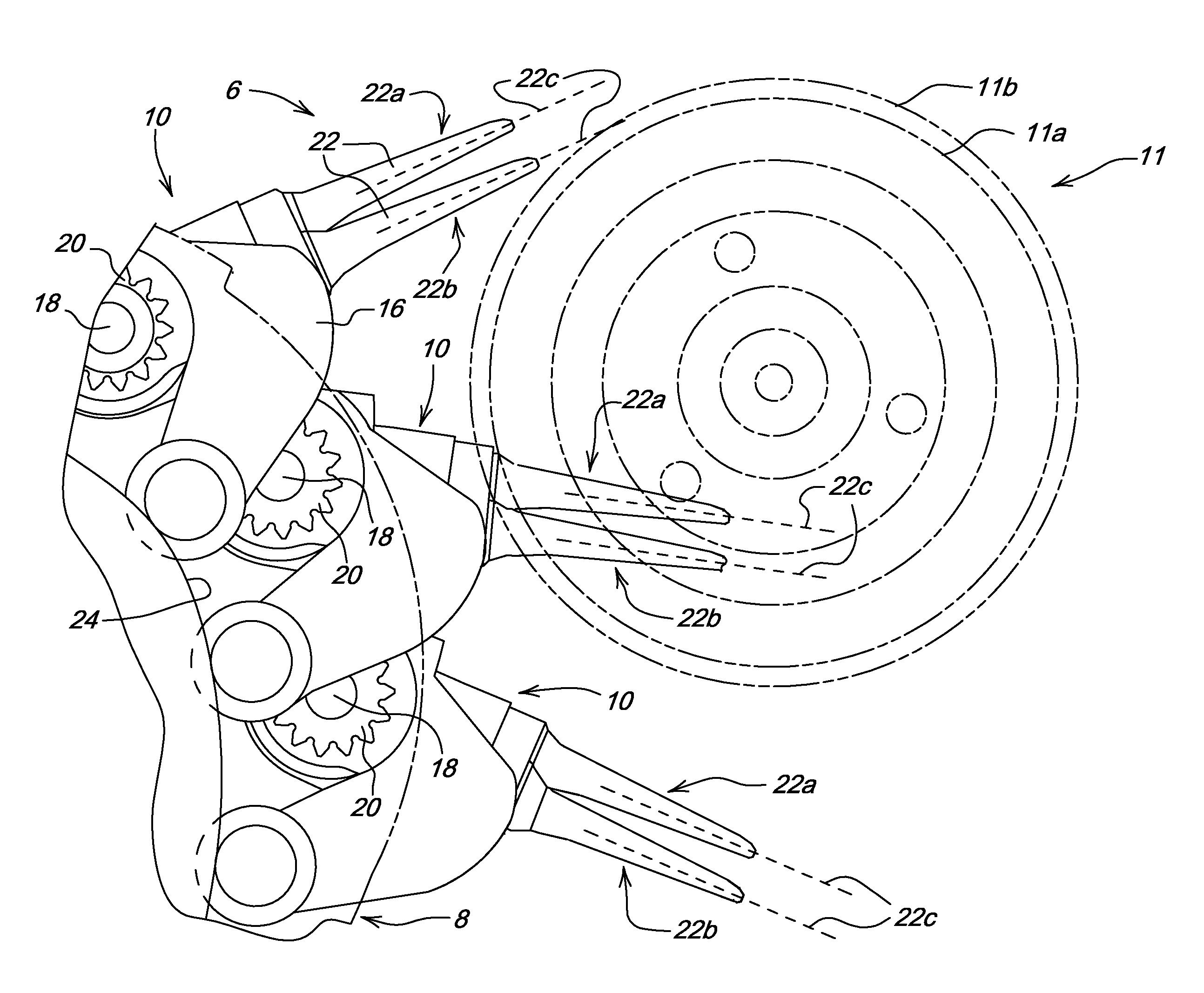
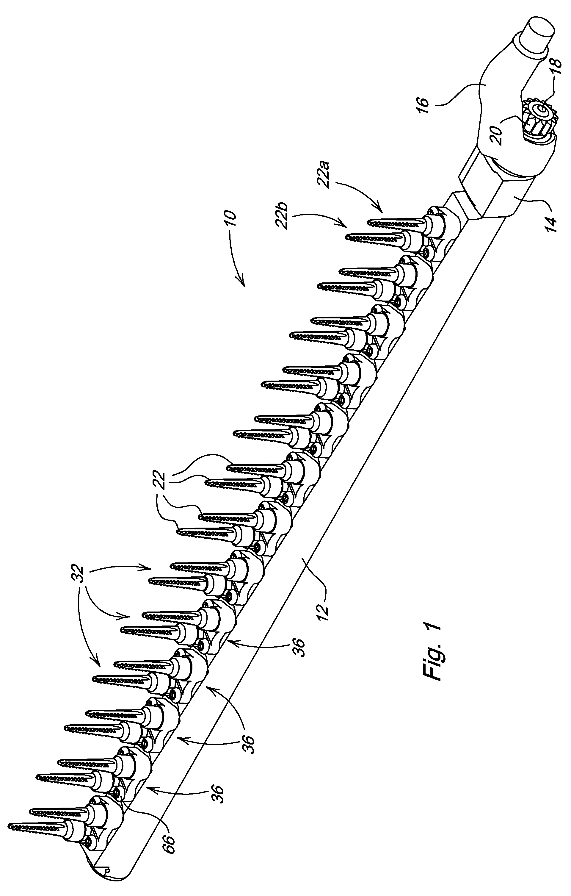
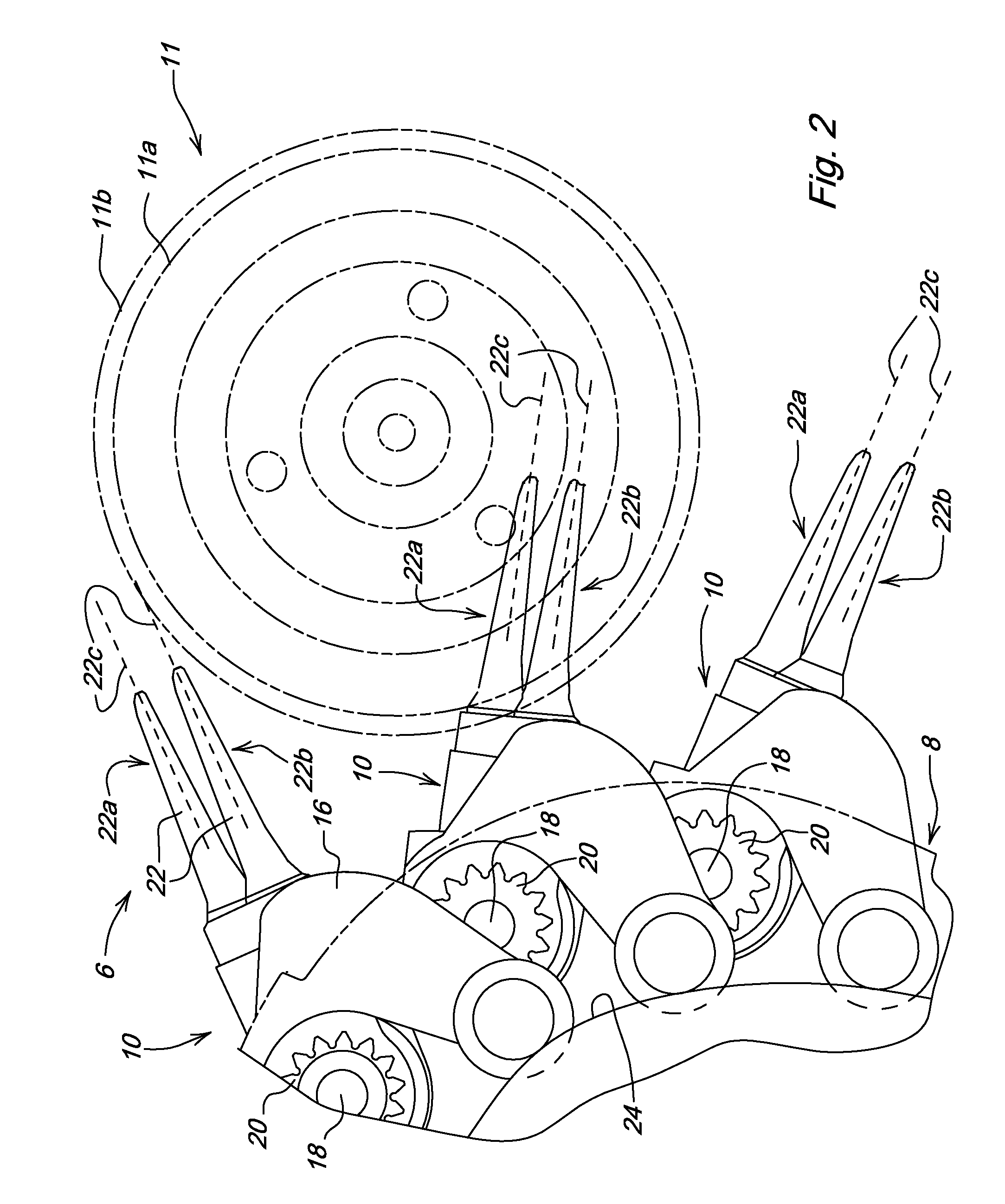
[0014]Referring to FIGS. 1 and 2, therein is shown a portion of a cotton picker row unit 6 having a picker spindle drum 8 with picker spindle bar assemblies 10. A doffer assembly 11 with doffer pads 11 a and 11 b is supported in the row unit adjacent the path of the picker bar assemblies 10. Each picker bar assembly 10 includes a hollow picker bar 12 with an upper end 14 adapted for journaling in the row unit drum head and receiving a cast cam follower arm 16. A spindle drive shaft 18 is rotatably mounted in the hollow picker bar 12. A driven gear 20 is fixed to the upper end of the shaft 18 for meshing with a conventional drive gear such as sun gear (see 21 of FIG. 5).

[0015]The picker bar assembly 10 includes at least two sets 22a and 22b of spindles 22 having axes of rotation 22c. As can be appreciated from the figures, the two sets of spindles 22a and 22b are nonaligned in the vertical direction and are offset on opposite sides of the drive shaft 18. The follower arm 16 is seated...


PUM


Abstract

A picker bar includes spindles which are nonaligned in the vertical direction to define two or more offset sets of spindles on the bar and increase the number of spindles per unit length of the spindle bar. A spindle assembly includes support carrying two spindles driven from a picker bar drive shaft by single drive gear. Driven spindle gears are spaced on opposite sides of the shaft axis to facilitate close spacing of the spindles.

Description

FIELD OF THE INVENTION[0001]The present invention relates generally to cotton harvesters and more specifically to spindle picker bars for cotton picker row units.BACKGROUND OF THE INVENTION[0002]Cotton harvesters often have a row unit structure with picker drums rotatable about upright axes adjacent a row-receiving area of the unit. The drum includes a plurality of upright picker bars having spindles which rotate in contact with cotton plants to remove the cotton. Corresponding spindles on the bars define generally horizontal spindle planes, with a typical drum having eighteen to twenty spindle planes. Doffers which rotate between the spindle planes in contact with the spindles to doff cotton wound on the spindles and direct the cotton towards air door structure for removal from the unit towards a basket or processor.[0003]A conventional picker bar includes a single row of spindles spaced uniformly in the vertical direction. Each spindle includes a gear end engaged by a mating bevel...

Claims


Application Information

Patent Timeline
Patent Type & Authority Applications(United States)
IPC IPC(8): A01D46/16
CPCA01D46/16
Inventor FOX, JEFFREY ROBERTPHILIPS, MARK S.
Owner DEERE & CO
Why Eureka
Try Eureka