Lightweight, portable cooking stove

Inactive Publication Date: 2009-12-24
HUGGINS TIMOTHY GREGG
View PDF84 Cites 11 Cited by
  • Summary
  • Abstract
  • Description
  • Claims
  • Application Information

AI Technical Summary

Benefits of technology

[0031]Alcohol-fueled stoves known to prior art often incorporate no means at all for adjusting the heat output. Those stoves which do provide a heat adjustment typically employ some type of snuffer in the form of a partial lid, cap or cover that is positioned in such a way to obstruct or interfere with the flow of fuel vapor as it escapes from the fuel vaporizer. This method of adjusting the heat output has several disadvantages. Positioning or adjustment of the snuffer can be a rather awkward undertaking and requires removing the cooking pot or reaching under it. This presents a danger of burning or scalding. Often the cooking pot must be completely removed from the stove and set aside while placing the snuffer. Obstructing the flame in this way also tends to produce a small hot spot on the bottom of the cooking pan and prevents the even distribution of heat for thorough and rapid cooking.
[0032]The portable, alcohol-fueled cooking stove of the current invention incorporates a practical, convenient, safe and simple mechanism for regulating the heat output of the stove. This mechanism is quick and easy to operate, and it achieves an effective control of the cooking process. This mechanism is integral with the stove and readily accessible on the outside of the stove. The heat output of the stove can be precisely adjusted without removing the cooking pot or risking burns, scalds or other mishaps.
[0033]This adjustment of the heat output is effected by metering and controlling the flow of combustion air both in volume and in location. This metering and controlling of the combustion air flow modulates the combustion process which is in contact with the fuel vaporizer, enabling the temperature of the fuel vaporizer to be regulated. That is, by reducing the volume and redirecting the location of the combustion air within the combustion chamber the fuel vaporizer can be caused to be cooled. As the fuel vaporizer is cooled, it generates less fuel vapor. This reduced flow of fuel v

Problems solved by technology

However, in the United States they have had limited popularity.
This limited popularity is primarily due to two factors.
The first factor that has limited the popularity of alcohol-fueled stoves in the United States is their overall poor performance.
In real outdoor conditions of wind and weather, these stoves rapidly become incapable of cooking a meal.
These stoves demonstrate a variety of forms and features that cause inefficient performance and wasted heat.
The overall inefficient performance of alcohol stoves known to prior art also causes an excessive consumption of fuel.
This is undesirable both due to the increased cost of operating the stove, as well as the increased weight of fuel that must be carried.
The second factor that has limited the popularity of alcohol-fueled stoves in the United States is the inability to effectively adjust the heat output of the stove.
Often these stoves provide no manner of heat

Method used


Image

  • Lightweight, portable cooking stove
  • Lightweight, portable cooking stove
  • Lightweight, portable cooking stove

Examples


embodiment 140

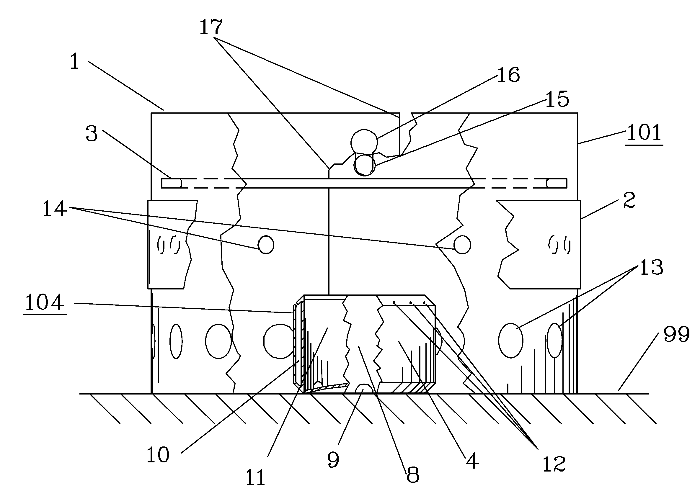
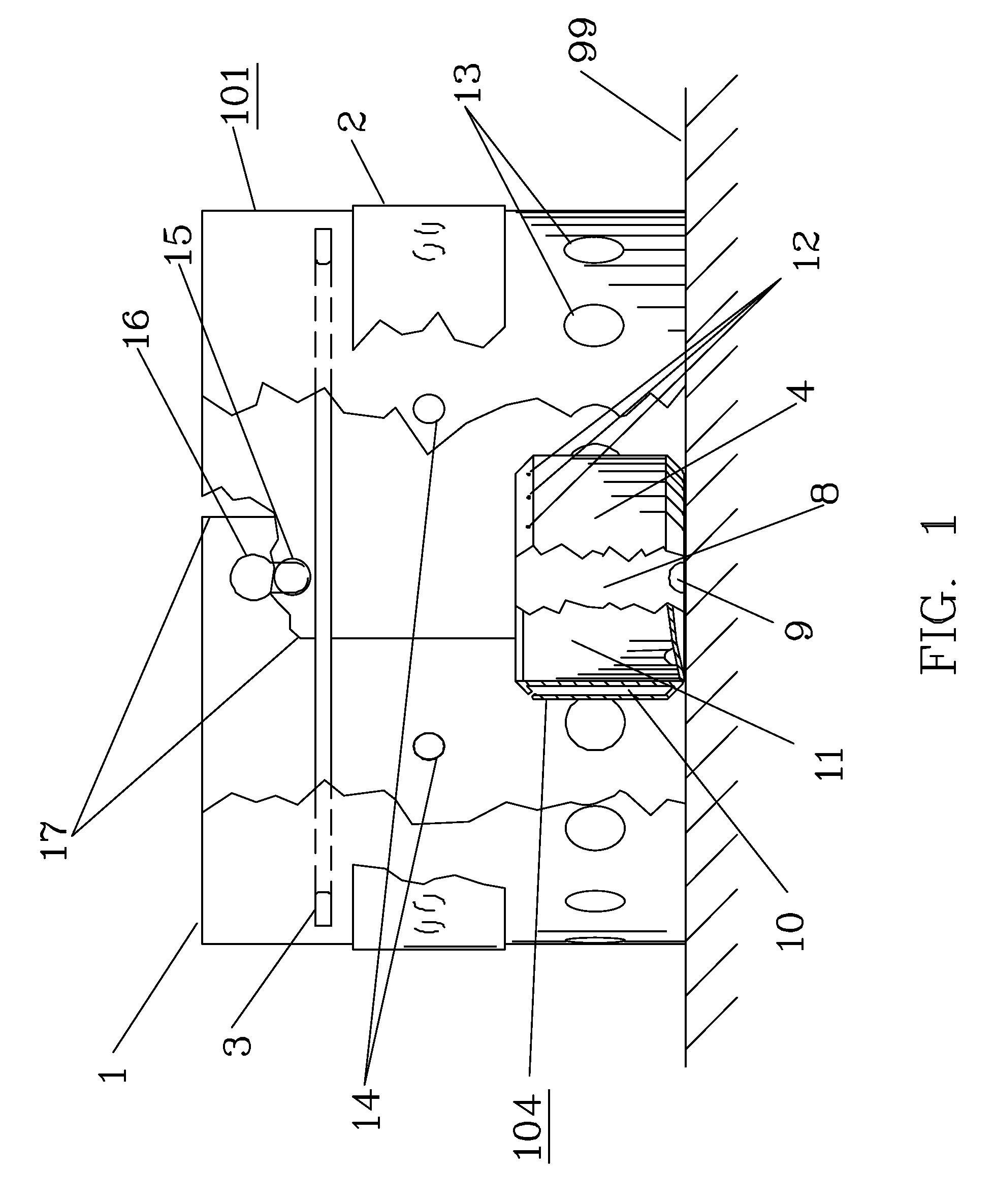
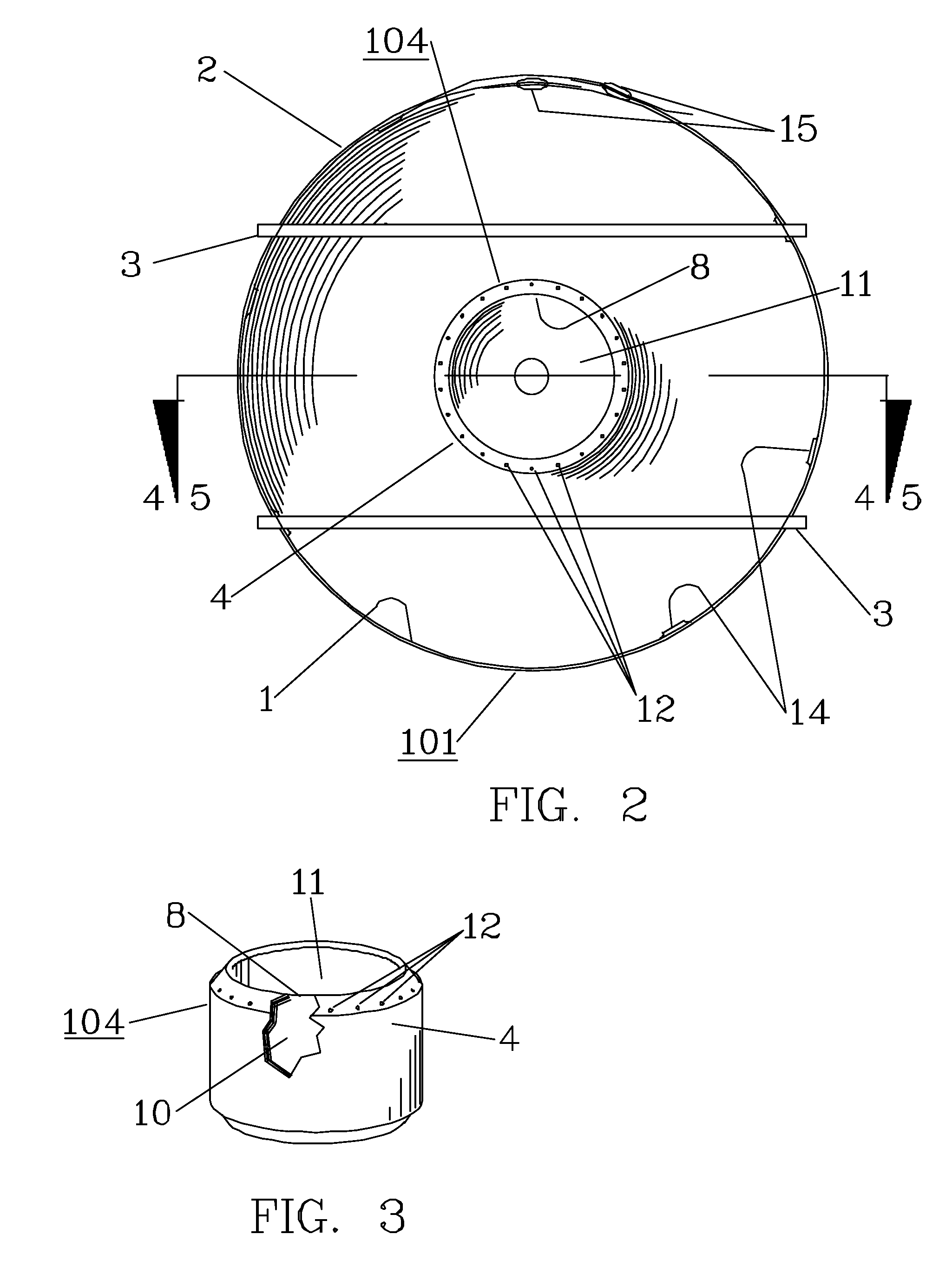
[0117]FIG. 15 shows a perspective view of an alternate embodiment of the fuel vaporizer 140. FIG. 16 shows a cutaway, sectional elevation view of this alternate embodiment 140. The alternate embodiment of the fuel vaporizer 140 is provided with cylindrical duct 53 coaxial with the body of the fuel vaporizer. This cylindrical duct 53 extends thru the center of the fuel vaporizer 140. This cylindrical duct 53 is adapted to provide a source of combustion air to the center of the fuel vaporizer 140. By providing combustion air to the center of the fuel vaporizer 140, complete combustion of the vaporized fuel can be effected.

[0118]The alternate embodiment 140 shares various features with the alternate embodiment 131 of the fuel vaporizer, and operates in a similar manner. The alternate embodiment of the fuel vaporizer 140 comprises a vessel in the shape of a shallow, cylindrical cup 49. This shallow, cylindrical cup 49 incorporates a double wall 50. By means of this double wall 50 the in...

embodiment 180

[0123]FIG. 29 shows a plan view of an alternate embodiment of the fuel vaporizer 180. FIG. 30 shows a cutaway, sectional elevation view of this alternate embodiment 180. The alternate embodiment 180 shares various features with the alternate embodiments 140 and of the fuel vaporizer, and operates in a similar manner. The alternate embodiment of the fuel vaporizer is provided with cylindrical duct 97 coaxial with the body of the fuel vaporizer. This cylindrical duct 97 extends thru the center of the fuel vaporizer 180. This cylindrical duct 97 is adapted to provide a source of combustion air to the center of the fuel vaporizer 180. By providing combustion air to the center of the fuel vaporizer 180, complete combustion of the vaporized fuel can be effected.

[0124]The alternate embodiment of the fuel vaporizer comprises a vessel in the shape of a shallow, cylindrical cup 91. This shallow, cylindrical cup 91 comprises a double wall 98. By means of this double wall 98 the interior volume...


PUM


Abstract

A small, lightweight, portable cooking stove that utilizes alcohol as fuel and is suitable for backpacking, hunting, camping and similar activities. The cooking stove includes a combustion chamber which encloses, contains and regulates the entire combustion process. The stove also includes an efficient fuel vaporizer, which is adapted to perform in unison with the combustion chamber, to effect the metered and efficient mixing of the air and fuel vapor. An integral, simple and convenient means is provided to vary the intensity and pattern of the heat output, thereby controlling the cooking performance of the stove. The stove achieves high heat output and efficiency, low fuel consumption, and superior cooking performance in a small, lightweight, portable, convenient, simple and integrated assembly.

Description

CROSS-REFERENCE TO RELATED APPLICATION[0001]This application is a continuation-in-part patent application of application Ser. No. 11 / 761,483 filed Jun. 12, 2007, currently allowed, which was a continuation-in-part of application Ser. No. 10 / 951,128 filed Sep. 27, 2004, issued on Jul. 24, 2007 as U.S. Pat. No. 7,246,614, the entire contents of which are incorporated herein by reference.TECHNICAL FIELD[0002]The invention is a small, lightweight, portable cooking stove that uses alcohol as fuel.[0003]Portable cooking stoves designed to use alcohol as a fuel are well known to prior art. These are used by hikers, campers, backpackers, hunters and others who have a need to boil water or cook a hot meal in remote locations or primitive conditions. As a fuel, alcohol has various advantages over petroleum based fuels.[0004]Alcohol is widely available, inexpensive, convenient, relatively innocuous and easy to handle. It can be readily repackaged and safely carried in lightweight plastic bottl...

Claims


Application Information

Patent Timeline
IPC IPC(8): F24C5/02
CPCF24C5/20F24C5/02
Inventor HUGGINS, TIMOTHY GREGG
Owner HUGGINS TIMOTHY GREGG
Why Eureka
Try Eureka