
Mist generating apparatus and method

a technology of generating apparatus and generating method, which is applied in the direction of watering device, burner, horticulture, etc., can solve the problems of increasing the problem, not all the working fluid being used is atomized, and the droplets are not uniform in siz

Active Publication Date: 2009-12-24
TYCO FIRE PRODS LP
View PDF100 Cites 54 Cited by
  • Summary
  • Abstract
  • Description
  • Claims
  • Application Information

AI Technical Summary

Benefits of technology

The present invention provides an apparatus for generating a mist by using a first transport fluid and a second transport fluid to create a high velocity flow that is applied to an atomized working fluid to produce a dispersed droplet flow regime. The apparatus includes an elongate hollow body with an elongate member co-axially located within it, with communicating openings that allow the first and second transport fluids to mix and flow through the apparatus. The elongate member has a convergent-divergent internal geometry that allows for a more efficient mixing of the fluids. The apparatus can also have one or more additional openings to further enhance the mixing of the fluids. The technical effects of the invention include improved mixing of the fluids, increased efficiency of the apparatus, and improved control over the size and distribution of the mist droplets.

Problems solved by technology

A problem with other conventional mist generating apparatus is that not all of the working fluid being used is atomized as it passes through the apparatus.
This can cause the creation of droplets which are of non-uniform size.
These droplets can then coalesce with other droplets to create still larger droplets, thus increasing the problem and creating a mist of non-uniform droplets.
In turbine cooling applications, for example, droplets which are over 10 μm in diameter can cause significant damage to the turbine blades.
However, such eliminators add to the complexity and manufacturing cost of the apparatus.

Method used


Image

  • Mist generating apparatus and method
  • Mist generating apparatus and method
  • Mist generating apparatus and method

Examples


example 1

[0063]The results presented in Table 1 below were obtained using a Particle Droplet Image Analysis (PDIA) system (Oxford Lasers Ltd (UK)), which makes use of a high frame rate laser firing across the spray plume into an optical receiver (camera). The PDIA system uses a spherical fitting algorithm (Oxford Lasers Ltd (UK)) to apply a diameter to the droplets in the image that it has captured.

[0064]The data presented below were measured 6 m and / or 10 m from each nozzle as this allowed good particle observation with the PDIA system, but also represented typical plume characteristics for each nozzle. Having determined the droplet sizes present in the plume, the data was further analyzed to calculate the Dv90, which is a common measurement parameter used in industry. The Dv90 is the value where 90 percent of the total volume of liquid sprayed is made up of drops with diameters smaller than or equal to this value (similarly Dv50 is for 50%).

[0065]The results summarized in Table 1 were gene...


PUM


Abstract

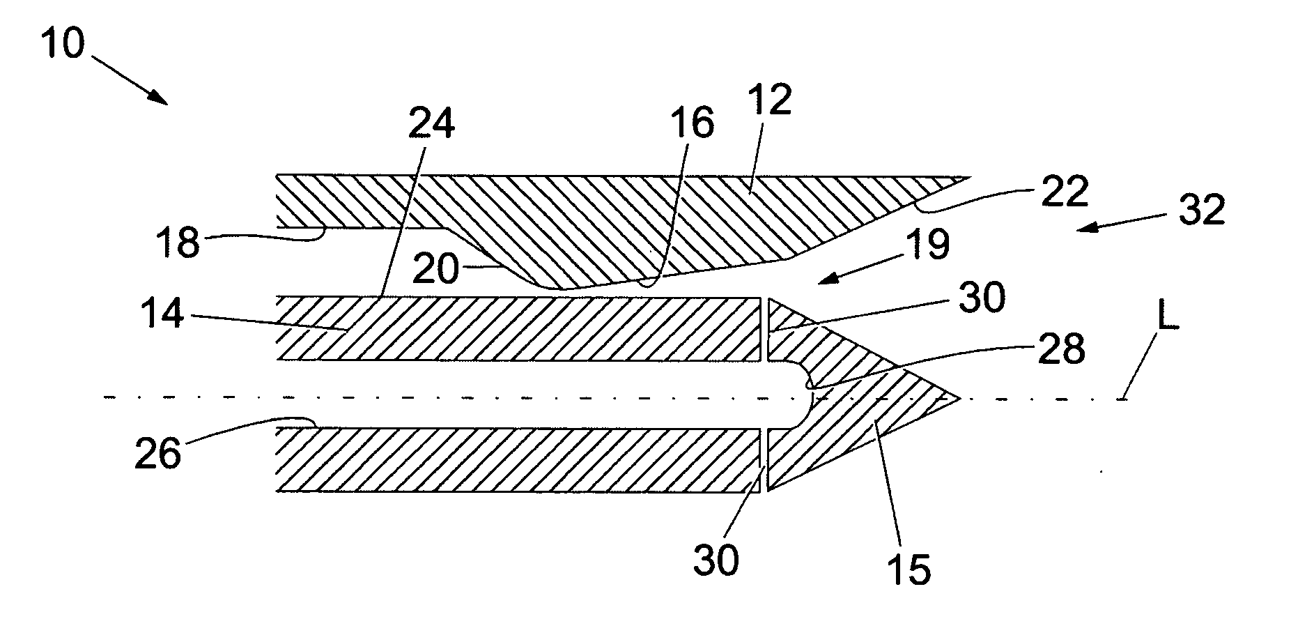
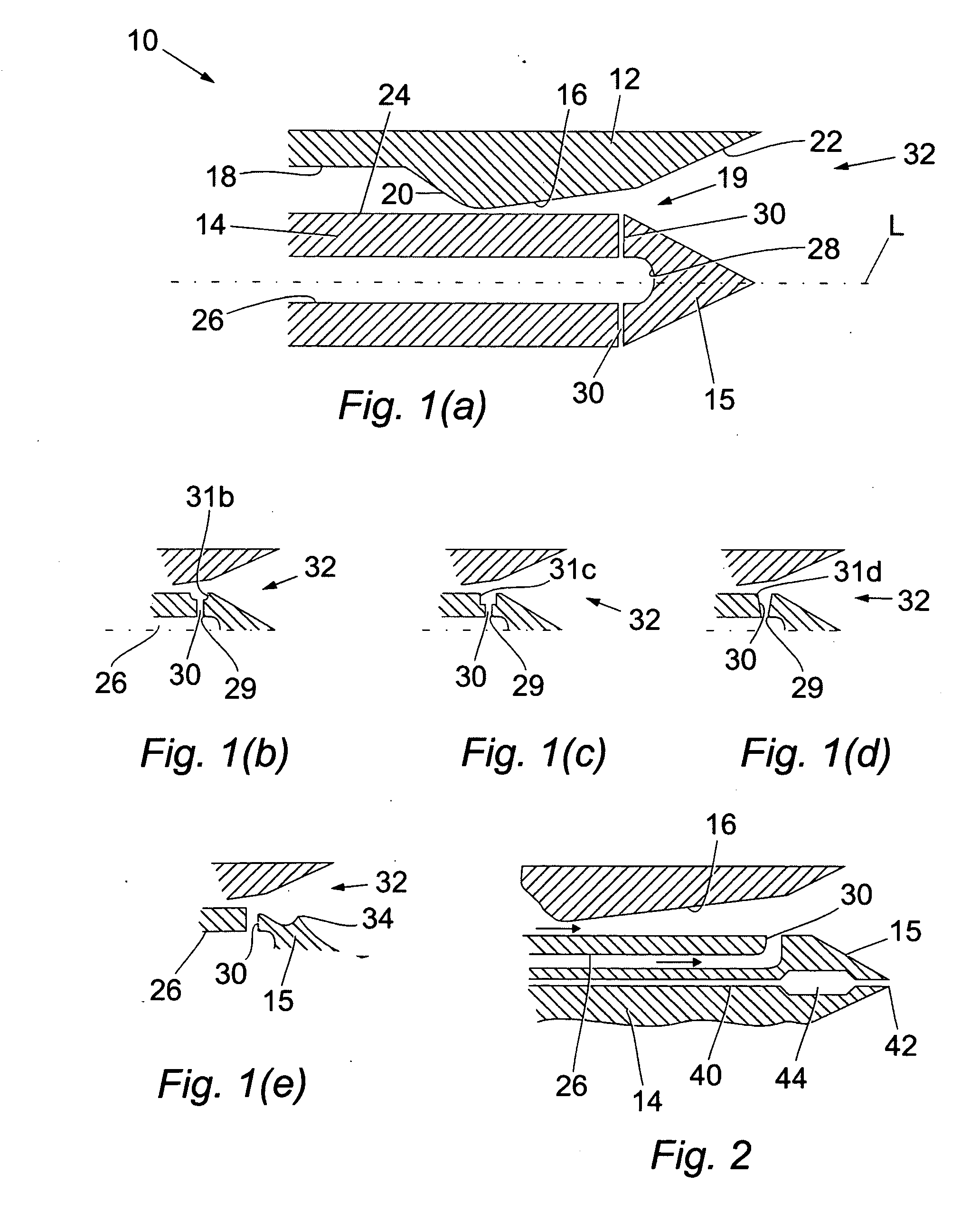
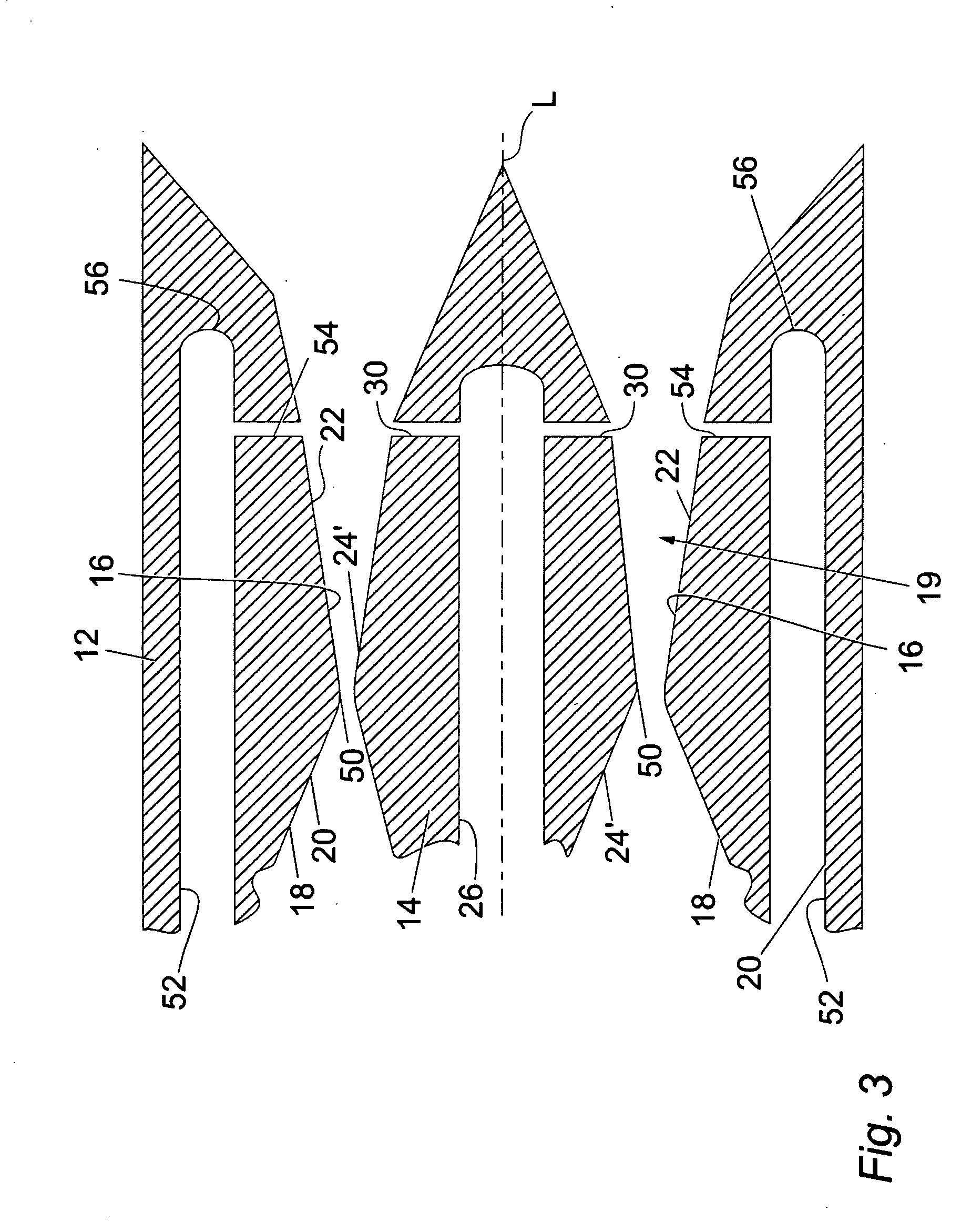
Apparati for generating a mist are disclosed. One apparatus is disclosed, which has an elongate hollow body (12) and an elongate member (14) located within the body (12). A transport fluid passage (16) and a nozzle (32) are defined between the body (12) and the elongate member (14). The transport fluid passage (16) has a throat portion of reduced cross-sectional area and is in fluid communication with the nozzle (32). The elongate member (14) includes a working fluid passage (26) and one or more communicating openings, such as for example, bores, annuli, and combinations thereof, (30) extending radially outward from the working fluid passage (26). The openings (30) permit a working fluid (e.g. water) to be passed into the transport fluid passage (16), whereupon the working fluid is subjected to shear forces by a high velocity transport fluid (e.g. steam). The shearing of the working fluid results in the generation of a mist formed from droplets of substantially uniform size. Methods of generating a mist using such apparati are also disclosed. Also provided are mists for fire suppression produced using an apparatus disclosed herein, as well as fire suppression systems that include any of the apparati disclosed herein. Further provided are devices, methods, and mists for various other applications including turbine cooling and decontamination.

Description

CROSS-REFERENCE TO RELATED APPLICATIONS[0001]The present invention is a continuation-in-part of international application no. PCT / GB2007 / 003492 filed Sep. 14, 2007, which claims benefit of priority based on Great Britain application no. 0618196.0 filed Sep. 15, 2006, the content of each prior application is incorporated by reference as if recited in full herein.FIELD OF THE INVENTION[0002]The present invention relates to the field of mist generating apparatus. More specifically, the invention is directed to an improved apparatus and methods for generating liquid droplet mists. Such apparatus and methods are useful in, e.g., fire suppression, turbine cooling, or decontamination.BACKGROUND OF THE INVENTION[0003]Mist generating apparatus are known and are used in a number of fields. For example, such apparatus are used in both fire suppression and cooling applications, where the liquid droplet mists generated are more effective than a conventional fluid stream. Examples of such mist ge...

Claims


Application Information

Patent Timeline
Patent Type & Authority Applications(United States)
IPC IPC(8): A62C31/02B05B17/00B05B1/00
CPCA62C31/02A62C99/0072B05B1/02B05B7/0458B05B7/0466B05B7/0433
Inventor FENTON, MARCUS BRIAN MAYHALLWALLIS, ALEXANDER GUY
Owner TYCO FIRE PRODS LP
Learn More